Thursday, November 30, 2017

CN/DM&IR 1916 Bridge over St. Louis River at Oliver, WI

(Bridge Hunter, no Historic Bridges, John Weeks III) For John Marvig, I found an Oliver Approach Bridge, but not his bridge.

DM&IR = Duluth, Missabe & Iron Range Railway

3D Satellite, 15 photos
Its center pier design is rather unique.
John Weeks III

rtands
CN wrapping up Oliver Bridge work
"A dozen different railroads have trackage rights over the bridge, resulting in very heavy traffic." [John Weeks III]

Update:
DOT
DOT
Innovative design of a swinging, double
-deck, Warren through/deck truss main 
span with rail traffic above and vehicular 
traffic below, created to meet 
challenging site conditions and federal 
regulation. This feature includes a 
center-pivot bearing mechanism for the 
swing span.

DOT
Design and construction of the double-deck, steel approach 
viaduct spans created to accommodate challenging site 
conditions and heavier loads.

Chicago District Cooling --- Big Ice Machines

Street View
In 1995, Commonwealth Edison started running a large ice making machine in the northeast quadrant of State and Adams Streets. The first floor IS standard retail outlets. But the remaining stories looked more like a parking garage. But instead of cars, those stories hold ice tanks, chillers and cooling towers. The chillers and cooling towers are industrialized versions of the unit you see outside homes and buildings that have central air conditioning. The chillers use an electric motor to drive a compressor and the cooling tower is like the coil and fan in the air conditioning unit. These chillers freeze the water in the ice tanks. They are run at night when normal demand is low. Back then, ComEd generated about 40% of its electricity with nuclear power, which was about twice the national average. Running the chillers at night helped maintain a load for the nuclear power plants. (Enwave is the current owner of this chilled water utility.) During the day the plant does not run the chillers. Instead, the ice slowly melts so that it can supply 34-degree water to buildings in the loop. This chilled water is run through heat exchangers in the customers' buildings. The water comes back to the cooling plant at 54-degrees, melts some more ice, and repeats the cycle. [The information for this posting comes either from a District Energy article or the Enwave web site.]

A satellite image shows the top of the building is three large cooling towers.
Satellite
Since the Montreal Protocol on Substances that Deplete the Ozone Layer went into effect in September 1987, in the early 1990s building managers were faced with the expensive prospect of either replacing or refurbishing their chillers. ComEd offered a third choice --- replace them with relatively cheap heat exchangers and buy chilled water from them. Needless to say, the new chillers used in the "ice machine" were of a modern design that did not threaten the ozone layer. The heat exchangers in the customer's building occupied 90% less space than on-site chillers. Removing a lot of equipment from the building not only freed up valuable real estate, it reduced a lot of the operational and maintenance expense for cooling the building. ComEd started with about 12 customers for that first plant in 1995.

Enwave-customer
The equipment, lights and people in large office buildings generate more heat than they loose to the weather, even in the winter. So cooling a large office building is a year around expense. In the summer, the air conditioning equipment could consume half of the building's electric supply. So using ice water for cooling not only provided a load for the nuclear plants at night, it reduced the the peak demand during the day. Reducing the peak demand not only means fewer power plants are needed, it means the grid to supply the electricity can be smaller (cheaper). Furthermore, selling ice water was an unregulated business. Regulated utilities were looking for opportunities to diversify into unregulated businesses.

This business model was successful enough that they built their second plant the next year.
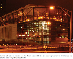
Thermal Energy owned the business in 2012 when the District Energy article was written. Enwave now owns the plant.
Note that the zoning laws here did not require retail outlets on the first floor.
P3 is inside the Blue Cross-Blue Shield of Illinois Tower. P4 is in the basement of the Merchandise Mart and uses river water instead of cooling towers to cool the chiller's working fluid. P5 does not have any ice tanks. All of these plants are interconnected with each other and the customer's building with a distribution network that has 8 trench miles. The size of the pipes vary between 12 and 30 inches. The different plants use different technologies and are interconnected so that the operators can choose which equipment to run based on availability of equipment, demand, and market conditions for electricity.

EnwaveChicago-system-operation
The details of the plants:
Plant P-1, State and AdamsStartup: May 1995
Current capacity: 20,000 tons, plus 66,000 ton-hr ice tank
Plant P-2, Franklin and Van BurenStartup: July 1996
Current capacity: 23,000 tons, plus 125,000 ton-hr ice tank
Plant P-3, 300 E. RandolphStartup: May 1997
Current capacity: 23,000 tons, plus 100,000 ton-hr ice tank
Plant P-4, Merchandise MartPurchased: June 1997
Current capacity: 20,000 tons, plus 24,000 ton-hr ice tank
Plant P-5, 300 N. Wabash BuildingStartup: June 2002
Current capacity startup and expansion: 15,000 tons
[EnwaveChicago-history
Another advantage of district cooling is that it is shared by buildings that have different uses such as office, residential, retail, hotel, and computer server farms. When the peak usage of one type of service goes up, the usage by some of the other types of service will be off-peak. This means the peak capacity of a shared utility can be smaller than the sum of the peak capacities if every building had its own chilling equipment. This further reduces the number of power plants and the size of the grid needed to serve the loop.

Using ice water from the utility also frees up space on the roof for LEED points (Leadership in Engergy and Environmental Design [Springfield]) such as solar panels and/or a "green" roof.

Street View
I read that the new Riverside Building (phto to the right) choose to use the district cooling solution.

[IDCS]
But the University of Chicago's Cummins Life Science building choose to replace their 1,020-ton chillers and 4160V electrical feeds even though it was very challenging (i.e. expensive) to fit the new equipment in while the old equipment was still running. Not only did they want to prevent the occupants from sweating and keep the computers running, they did not want sensitive biological research projects to die. [IDCS]


When I tried to track down a reference I forgot to include, I also found the following: "Chicago’s [district] is the largest contiguous system in the nation, if not the world, with fourteen miles of pipe and an eight million gallon capacity." [SustainableChicago]

Tuesday, November 28, 2017

Lakeview Water Supply Pump Station (N1)

(Satellite, the second station was torn down in the 1979)

Before Chicago annexed the Lake View Township, it was responsible for its own water supply.

Chicago Tribune
Jan 22, 1892, Page 1
(access)
Unlike Chicago, which used a tunnel and crib to supply its pumping station, Lake View used a pipe with a screen over the intake. The screen is about 6-10 feet below the surface. Ground up ice and snow picks up sand from the shore and when it floats over an inlet, it is so heavy that the strong current sucks it toward the screen.
Chicago Tribune
Jan 22, 1892, Page 1
When the screen gets plugged, a diver goes out in a rowboat to pick and scrape the ice away. The men in the little boat keep the huge cakes of ice from crushing the boat or cutting the tube which supplies the diver's air. They were working on a tunnel and crib to replace the pipes, but work was going just 6-7 feet a day since they were deep enough that they were digging through limestone rock. Some thought the tunnel should have been more shallow so that they would be in blue clay were the digging would go much faster. The beginning of LakeView Historical Chronicles shows the crib that was eventually built for Lake View.
The original Lake View Township Pumping Station operated from 1876-1913 in the northeast quadrant of the corner of Clarendon and Montrose Avenues.
Photo from HAER ILL, 16-CHIG,106--2 from il0420
See also an 1895 photo
Originally it had a 2.5mgd "Flanders" high pressure condensing engine having two 15"x15" steam cylinders with two double acting pumping ends with 14" diameter plunges and 20" stroke. In 1884 a Worthington duplex horizontal compound condensing engine of 5mgd capacity was installed. In 1888 a Gaskill 12mgd unit was installed. In 1892 a second Gaskill 12mgd unit was installed.

Chicago annexed Lake View in 1899.  During 1907-09 a new engine house was built to provide four more pumping stations. Details of what was put in the annex start on page 2 of the il420 data pages.
Work started on a replacement station in 1913. It was operational from 1915-1959. (Two temporary turbine centrifugal pumps with a capacity of 20mpd each were used while the old station was torn down and the new one built.) The new one was torn down in 1979.
Photo from HAER ILL, 16-CHIG,106--1 from il0420
It used 3 Nordberg pumping engines and a Bethlehem Steel pumping engine, each with a capacity of 25mgd.
1938 Aerial Photo from ILHAP
Only this station and the Chicago Pumping Station had coal delivered by truck instead of by rail cars.
The HAER report has a lot of construction photos. As an example here are three photos concerning the construction of the pump engines.

Photo from HAER ILL, 16-CHIG,106--18 from il0420
 NO. 4 ENGINE
[Plumbing and flywheels are installed]

Photo from HAER ILL, 16-CHIG,106--20 from il0420
NO. 4 ENGINE. CYLINDERS & RECEIVERS INSTALLED

Photo from HAER ILL, 16-CHIG,106--60 from il0420
NORDBERG MFGR. CO. ERECTION SHOP


CA&E Yard in Wheaton, IL

(Satellite)
Frank Smitty Schmidt posted
Aerial view of the CA&E yard in Wheaton, circa 1950.
Frank Hicks I'd say c1960, not 1950. The photo was taken after abandonment. The 450s are grouped in front of the shop where they could be easily viewed by potential buyers.
David Daruszka The shops were between present day Liberty, Childs, N. Gable and Carlton. I believe the phot view is Northwest.
Frank Smitty Schmidt commented on his posting
You can see it in this 1939 aerial.
This was actually east in Glen Ellyn. The view is looking West.
Frank Smitty Schmidt posted
Chicago Aurora & Elgin overtaking a Chicago & Northwestern train near Wheaton. Year unknown.
Jack Franklin Seeing as how the C&NW used steam engines in commuter service until 1956 and the CA&E used wooden cars till the end, this picture is literally timeless.
John Markl Noting that the CNW had only two tracks in this photo, this would have to go WAY back in time.... Also, while the CNW ran left-handed, the Roarin' Elgin did not....so the probably just passed each other in opposite directions....
Patrick McNamara commented on the above posting
...and here is the location of this shot...............

Monday, November 27, 2017

Trail/Rock Island Bridge over Arkansas River in Little Rock, AR

(Bridge Hunter (a comment provides a nice history and some photos of the swing span being replaced by a lift span in 1970), 3D Satellite)

20181221 7162
The photo is overexposed because the aperture in my Nikon 18-55mm lens broke wide open and I was having trouble compensating for that. The building on the right is the end of the Bill Clinton Library and Museum. (It was closed when we were there because the federal government was shutdown concerning $5 billion for a border wall.)
[Posted as an example of how a lift bridge can be turned into a trail.]

Fourth photo posted by Brian Wunderlick
Note how the trail decking is on an incline so that the lift span can permanently remain in the up position for river traffic.
Street View
Update:

Bud McDonald posted
Formally the Rock Island Rail Road Bridge in Little Rock Arkansas, today it's the Clinton presidential park Bridge.

Mark Silverberg posted
About a week ago, I posted a photo of the former Rock Island station in Little Rock from a different angle, one off of the top level of a relatively new downtown parking garage. Here is another shot from the same top deck, just north of the station is the former Rock Island bridge over the Arkansas River.
Paul Chandler That's a cool bridge to walk over

This photo of William J. Clinton Presidential Library is courtesy of TripAdvisor

Michael Young Flickr 1989 Photo, CC BY-NC-SA 2.0
Missouri Pacific tracks in foreground had recently become Union Pacific. Today they're gone. But the bridge survives! See satellite view on map, and links to bridge site, now a part of the Clinton Presidential Library complex.
Thomas R MachnitzkiCC BY 3.0
Clinton Presidential Park Bridge in Little Rock Arkansas.

There are several links at the bottom of this page concerning this bridge.


Central Park Water Supply Pump Station (C4)

This station was across B&OCT's Homan Yard from Sears' distribution center. This is the smokestack I saw in the background of some of the pictures I took where the Sears buildings used to be. Like the Springfield Station, this station should be converted from steam turbines to electric motors. Construction is estimated to cost $80m and begin in 2015 or 2016. [SlidePlayer, Slide 23, pptx format]

3D Satellite
Street View
A Flickr photo indicates this station was built in 1899.

Intelligent Design & Construction Solutions (source)
The Central Park Pumping Station Electrification project is to convert a steam-powered pumping station to electrically driven pumps, and rehabilitate and upgrade the electrical services to the pump station. Built in 1899, it is one of several large City of Chicago steam-powered pumping stations. IDCS was tasked by Greely & Hansen Engineers, the lead Engineering firm, to provide design and construction services for various tasks of the project. IDCS developed a technical analysis with life cycle cost of the alternatives available to drive the pumps. These included throttling, eddy current drives (ECDs), slip power recovery with wound rotor motors (SPR), and variable frequency drives (VFDs). The alternatives were presented in several workshops, and VFDs were finally selected. Detailed design of the pumping station’s auxiliary systems including: CCTV, Access Control, Telephone, Internet, Public Address (PA), Intercom, and Emergency Lighting. The CCTV (over 50 cameras) and Access Control Systems are integrated into the Central Security System at the Jardine Water Purification Plant. The telephone and internet were each linked to the appropriate city government wide system. The Emergency Lighting system was developed using a central UPS and egress lighting which doubles as night lighting. This eliminated the need for independent battery units and the associated maintenance headaches. Before the cut-over of steam-driven pumps to electric pumps, new temporary generators were needed for complete support of the new electric pumps during construction. IDCS is also providing bid services and services during construction.
I guess the Springfield conversion made the correct decision to use Variable Frequency Drives. It seems to be a waste of money to study which type of motor to use each time they convert one of their four steam plants to electricity.

3D Satellite
Because this site is not large enough to have a coal storage pile like the Western Avenue Station did, I assume the tall, skinny rectangular building on the east side of the plant is for coal storage. In fact, you can still see the hole in to which hopper cars on an industrial spur from Homan Yard would dump the coal.
1938 Aerial Photo from ILHAP
That storage facility did not exist in 1938. I remember since moving to Illinois in 1973 that there was a significant coal strike because I was glad that, at the time of the strike, ComEd generated about half of its power with nuclear stations so the impact of the coal strike was reduced. (The other half would have been coal because that was long before abundant natural gas and renewable energy was available.) So maybe the storage facility was built in anticipation of strikes. I wonder how many weeks that storage capacity would support.

A comment on a B&OCT posting:
Les Wuollett Use to spot coal cars at what we called "The Pump" when I worked at Homan Ave yard.


Sunday, November 26, 2017

1903+1951 Rock Island Bridge over Kansas River in Topeka, KS

(Archived Bridge Hunter; Satellite)

Until Sep 2024, I erroneously called this the Santa Fe Bridge. The Santa Fe Bridge is further downstream (East).

They would have parked the stone filled cars on the bridge when the flood was predicted to reduce the chance that a span is pushed off of its pier.
Third photo posted by Brian Wunderlick
Topeka Ks, July 1951 CRIP bridge pier failure over the Kansas River
Chad Henton The bridge and the cars are still in the river to this day. River is very low right now, easily seen.
Chad Henton The south half of the current bridge seen on the left side of this photo is still in use( built in 1904), the two spans seen failing here where replaced after this photo.
Someone must have cleaned up the bridge and cars because I don't see them in the satellite image.

You can see that the grade of the railroad is below the top of the levee. A BridgeHunter comment confirms that the structures on the piers can lift the trusses up during a flood event. And that capability was used during the 1993 floods.
Street View, Jul 2021

A BridgeHunter comment said that you can still see the lost trusses. I presume that is here. Another comment said these may be from the 1903 floods. That the trusses from the 1951 floods were salvaged.
Satellite

Anonymous comment on Bridge Hunter:
In past years I did much research on the 1951 flood. The spans in the river were collapsed the evening of July 14th, 1951. This bridge was built in 1903 to replace a bridge that was completely destroyed in that flood. In fact, all bridges over the Kansas river were destroyed in the flood of 1903 with the exception of the 1900 built MoPac bridge in Kansas City, which still stands today and is in use. If you search historic images and special collections, aerial photographs exist of this bridge swamped in the July 14th flood waters with weighted railcars and locomotives parked on it in effort to weigh it down. The following morning, additional ones were taken and the center spans are missing. The paper in Topeka published an article too that day I'd read with photos detailing how this bridge and its companion AT&SF; bridge downstream about a 1/2 mile both lost center spans and all the locomotives just hours apart when the water was at maximum discharge levels.

AT&SF; pieced their bridge back together with different span types and one of them is clearly shorter as well. Rock Island rebuilt this bridge with identical spans (as you pointed out). Much like ATSF, RI left the damaged spans and submerged locomotives in the river where they still remain. The Kaw is also not classified as a "navigable waterway" by the Coast Guard so removing those spans would be a waste of money, and we all know that railroads don't like spending that. RI however did go a step ahead of ATSF, and installed a flood jack system (the sheds atop those arches) and reinforce the piers on this bridge in years after. Three bridges in KC (one also owned by RI at the time) also have a flood jack system that were installed after the 1951 flood. These were most recently used in the flood of 1993.

In closing, I've never seen any photos or info on this bridge's predecessor, but I can say that the spans in the river were built in 1903 with the bridge and not from an earlier one. If looked at in person (from Topeka Blvd) and google earth, it is clear they are Warren trusses as is the rest of the bridge. If I had to guess I'd say the first one was probably an old lattice truss similar to the 1899 Blue River bridge in Manhattan or perhaps even a wood pile structure. Whichever the case, the 1903 flood was much less severe in comparison to '51 or '93, so it was pretty weak to have been completely wiped out. Sorry to ramble on, wanted to share at least what I knew on the subject....... :-)

Springfield Water Supply Pump Station (C2)

3D Satellite
While researching the Western Avenue Pump Station, I learned about the Springfield Pump Station. There is quite a bit of information on it because, of the four steam powered pump stations, this one has been converted from steam to electricity. This satellite image caught the plant after the two new buildings with the green and solar panel roofs had been built but before the chimney had been dismantled at the end of 2015.
Ryerson & Burnham Libraries
1938 Aerial Photo from ILHAP
The station was built in 1901. It had a building to add chlorine because it was supplying water to the water mains before the Jardine Purification Plant was built. The chlorine building was one of the buildings that was removed to make room for the new electrical equipment buildings. The boilers originally used coal, but they were converted to natural gas with fuel oil backup in 1953-54. The stack that was recently dismantled was 240' high with a 9.75' top diameter. It was built in 1948. [AECOM]
AECOM, Slide 6
The station has five horizontal centrifugal pumps, 3@80mgd (I assume million gallons per day) and 2@60mgd. They were driven by variable speed steam turbines to support pump-on-demand operation. That is, there is no water storage (water towers) in the distribution system. The turbines were replaced with variable frequency drive motors: 3@3250hp and 2@2250 hp. There are five 2000 kW diesel standby generators. [AECOM]

The conversion cost was estimated at $64.6m and will reduce carbon emissions by 17,380 tons per year. "Electricity will come from two separate ComEd sub-stations, to ensure redundancy and reliability." The green roof and solar panels are to help obtain LEED-certification. [CityOfChicago] (LEED = Leadership in Energy and Environmental Design [AECOM])

SlidePlayer, Slide 20
The cost was at least $73m. The estimated annual savings is $4.5m due to reduced energy, maintenance & personnel savings. After conversion, the plant can be operated remotely. [SlidePlayer, Slide 20]
Since this is the only conversion that has been completed so far, this Meccon article should be about this station. The second photo below is consistent with this station. But the first photo and the details are either from a different station or the plans described above changed significantly.
Meccon
Finished Product – Five 48 x 32 Water Pumps reconditioned and drives converted from steam turbine to 4200HP electric motors

Meccon
New 40,000 square foot electric building for pumping station. Includes 3-fuel powered electric generators and 5-VFD's for new motors

William Smiljanich posted
Iconic smokestack of the Springfield Avenue Pumping Station at Springfield Ave and Bloomingdale Ave to be taken down to reduce the station's carbon footprint. This is all part of a multimillion update and renovation of the pumping station. Good news is that when they are done, they city will renovate and expand Beilfuss Park, next door.

http://www.gwpc.org/…/default/files/event-…/22Hall_Steve.pdf
[The conversion of the pumping station has already happened and is described above. ]

William Smiljanich Just west of the 606 trailhead.
William Smiljanich Thanks Val. Sadly that chimney will be gone soon.
[This comment was made five years ago. But a current satellite image shows that it is still standing.]
Al Moreno That's awesome , yeah it spews a black soot onto cars, so it can't be good to breath in! Glad it's going away. And the expanded park will be nice in addition to the bike trail on the train !
[The photo was taken west of this signalling bridge looking East. ]
Val Gintter commented on William's post
Here's a shot I took in 1950 in the opposite direction from Lawndale Avenue. I took it with a Kodak Baby Brownie Special (designed by Walter Teague). Note the commuter train about to turn south onto the main line.