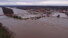
Sunday, June 29, 2014

Excitation Current

Synchronous AC generators such as those in large power plants need a DC current flowing through the rotor windings to create a steady magnetic field. Mechanically rotating this magnetic field through the stator windings induces the AC current generated by the plant.

Modern facilities produce the DC current by rectifying power from the grid. That is why they cannot darkstart. But hydro-electric plants in the early 20th century had auxiliary generators to create their excitation current because there was no grid to tap. They were the sole source of power for their market.

The Keokuk Powerhouse has two of the following 2,200 horsepower AC Generators spinning at 125 rpm, each connected to a bus that serves half the units. The apparatus in front is part of a specially designed oil-pressure governor. These generators are dynamically excited and the casing on top houses the exciter circuitry, which is part of the rotating machinery.

Used with permission from Jim Rabchuk
Each main AC generator, below is 13 of the 15 units, has a motor that taps that bus to drive a DC generator. The output of the DC generator is connected to the field windings using brushes. So the main AC generators use static excitation.

Used with permission from Jim Rabchuk

Below are the two 220 hp auxiliary DC generators that were installed in the Lockport Powerhouse of the MWRD in 1934. These replaced the original 3 units installed when the plant went operational in 1907. The original exciters would generate 632 hp at 300 rpm.

20140614 0324

The 1907 Crocker-Wheeler AC generator below is statically excited by the auxiliary units and can produce 4,000kw at 6.6kV.


These units are no longer used, but they were left in as museum pieces because now only 1,500 cfs can be used after the other Great Lake states and Canada sued Chicago in the 1930s for drawing too much water out of Lake Michigan. The plant was designed for 10,000 cfs, and ran at 5,000 cfs until the lawsuit. Here is an overview of the "old half."


And a closeup of the three remaining 1907 units.


I could not figure out how a horizontal shaft would work until I found the following diagram.

US Goverment, HEAR IL-197-C from il0979


This diagram depicts the turbine with just 4 stages, which were installed in 1945. The original turbines had 6 stages. A turbine would generate 5,092 hp at 165 rpm. 5 of the turbines contained Wellman-Seaver-Morgan wheels with 54" Jolly-McCormick runners. Two of the units used S. Morgan Smith wheels. Unfortunately, I don't know what a wheel vs. a runner is.

The last horizontal unit retired was in 1976, and it was left in situ. Where they removed the old generators, you can see the hole they plugged up through which the 12-inch shaft used to go. In addition to these two units, the turbine has also been removed from the unit on the far end even though it still has its generator.


These three units that no longer have their turbines have had their intake gates replaced with 3 sluice gates per unit that are controlled from the MWRD headquarters in Chicago to help regulate the canal level in response to an influx of storm water.

Update: 1912 ComEd Power Station.

By the mid 1900s, there were enough different power stations in the country that the gnerators derived their excitation current from the grid. No one dreamed (more accurately, nightmared) that the entire grid might go out. But it did in the Northeast in 1965. I remember that ComEd had a big plant near the East River. This allowed them to bring a naval ship near the plant. They used a generator on the ship to provide the excitation current to get one of the power plant's units running again. (I always wondered what the "jumper cables" that they strung from the ship to the generator looked like.) Then they could use power from that unit to provide excitation current to start up the remaining units and power plants in the Northeast. But before they started that first unit, they had to isolate a service area that was big enough to provide load for the generator but not so big as to overload it. And as they brought more units on line, they had to adjust the service area to keep the supply and demand of electricity balanced. New York had blackouts in 1977 and 2003 as well. I assume by then that at least some units had gone back to using auxiliary generators rather than the grid so that they no longer had to find a navy ship to restart the grid. (It appears the Brooklyn Navy Yard is no longer a navy yard. It is a couple of development projects and a museum.)


A 22:48 video of a steam plant with Crocker-Wheeler equipment (source)

Chris Austin posted
Beaver Valley . 2012 I was on the Generator/ Exciter crew. Photo of exciter before the doghouse was back over it.

These three photos are the excitation equipment for the Georgetown Steam Plant.
1, HAER WASH,17-SEAT,2--20
20. GENERAL VIEW OF MOTOR GENERATOR USED FOR EXCITATION. ORIGINALLY PROVIDED DC POWER TO INTER-URBAN LINES

And the above excitation generator had its own excitation generator!
2, HAER WASH,17-SEAT,2--21
21. GENERAL VIEW OF MOTOR GENERATOR WITH SMALLER GENERATOR IN FOREGROUND TO PROVIDE EXCITATION FOR LARGER DC UNIT
 
3, HAER WASH,17-SEAT,2--34
34. VIEW LOOKING NORTH NEAR UNIT #2. MOTOR GENERATOR ON RIGHT AND STEAM EXCITER GENERATOR ON LEFT
[I think the caption has left and right reversed. Those pipes on the right look like steam power to me.]


Friday, June 27, 2014

Typewriter vs. Keypunch vs. Keyboard

20140812 584c, sorry about the blur.
The ISO was up to 800, but I see the shutter speed was 1/6.
The posting on Tank Car Safety and a post I have been working on for the Keokuk Dam and Powerhouse are effectively small research papers. And I have been thinking about why I'm having trouble writing them. The last time I wrote a research paper, I used a typewriter and 3x5 notecards. On the other hand, I did not have spell check, a web search engine, and satellite maps. My current issue is that I have to invent an electronic version of notecards.

Another problem is that the monitor provides such a small window into what I have written. For years I had a monitor that was 1600x1200 pixels from work. But I had to surrender that monitor when I retired. And now all of the monitors that I could buy are shorter. The monitor I'm currently using is 1920x1080. It is interesting how much impact loosing a couple of inches of height has had on my comfort level when editing a post. But the "research" posts grow large enough that even a larger monitor would not help.

So I printed what I had written so far so that I could spread it out on a table and see what I had and try to figure out a new structure for the post. In the past, when learning another persons program (or relearning one of my own), I would print it and go find a conference room table to lay it out on. Think about how many more pixels are on several pages of paper compared to a monitor. No wonder it is so hard to see the "big picture" with a monitor.

And then I thought about cutting apart the various paragraphs and pictures so that I could physically rearrange the content. This reminded me that the origin of cut&paste is not ctrl-X/ctrl-V but rather newspaper editors cutting up columns of typeset text to paste them on pages.

And my use of a typewriter for research papers reminded me of a meeting I had at work in the late 70s. Keep in mind that the PC was not developed until the mid-80s so keyboards did not exist. We had terminals that integrated the input (keys) and output (CRT) as one unit. In that meeting I mentioned that I had keypunched a memo. A colleague asked me "When was the last time I used a keypunch?". He thought I should have used the verb typed instead of keypunched. I turned to him and asked when was the last time he used a typewriter. I had certainly used a keypunch more recently than a typewriter, and so had he. Fortunately the introduction of the keyboard in the 80s also introduced the verb keyboarding so that I now don't have to choose between antique terms for the activity of banging on keys.

So we don't have to go back to the 1800s and early 20th century to do Industrial Archeology of relics. Typewriters and keypunches became relics in the 1970s with the advent of text processing (troff and TeX are the two I used) and then word processing (What You See Is What You Get or WYSIWG) programs. In fact, the text processing programs have also become relics.

Concerning punch cards, during grad school, you could tell who was doing some serious programming because they needed a box (2000 cards) to carry their program. In fact, I had a program that required me to use a drawer (3600 cards). And I remember that I could grip about 700 to 800 cards.

We got rid of our typewriters years ago. I used to have punched cards and a 1200-foot reel of magnetic tape from college up in the attic. But they got thrown out several years ago. So there are no pictures for this post of antique computer media.

Update:
John L Huck shared
Manny Day I worked third trick at West Liberty IA the summer of 1972. Traffic was usually light (except for when a bridge on the spine line north of DM washed out, and all traffic between Des Moines and MN was routed through West Lib) so I copied train orders on a typewriter like this. 37 copy flimsies. Then I would call Ralph Fee (DM dispatcher) away from his coffee to read them back. All set for the next day's handups. Can anyone post interior photos of the West Lib operator's station, either from the 20th Century or as restored?
[I knew train orders were called flimsies. If they had to roll in 37 sheets and 36 carbon papers, no wonder the sheets were thin.]

Chris Percell posted
My recent find, All set to copy.
Kyle Graft trains run on little pieces of paper not much thicker than toilet paper ....how did it ever work......
Kyle Graft i had to take a typing test on a manual typewriter when i was interviewing for a Managment Job for the Katy in 1981...
J Pete Hedgpeth There was a time when the use of the typewriter for train orders was not allowed. Look at the old "operator's script" on orders back in the late 1800's and early 1900's.. I don't know when the use of typewriters was begun, but it was of fairly recent..probably 1920's or so. I'd be glad to hear from somebody who knows with a reasonably high degree of accuracy. That old operator's script was beautiful, but in some cases hard to read. BTW...I'm assuming that most of you guys know why train orders were written on transparent paper and were called "flimsies".There is a specific reason why that kind of paper and reproduction was used.
John Stell Order could be read by holding up to firebox on steam engine so they could have light to read it,.
Bill Neill Kerosene and electric lanterns also worked very nicely to illuminate the backside of train order tissue.
J Pete Hedgpeth John Stell you get the prize..Your answer is absolutely correct...However the firebox was not the only light in the cab..There were gage lights and usually an overhead light, but they were dim and somewhat unreliable. Whatever it was the idea was, as you stated..to allow the light to come through from the back rather than trying to make the writing out via a light shining on the face of the paper. Just as a little "aside"..it was many years after I became aware of train orders that it dawned on me that the writing on the flimsy was ON THE BACK rather than the front of the paper. This was accomplished by use of "double face" carbon and/or just putting the carbons in "upside down" to get the writing on the back..This reduced...or, at least, minimized the possibility that the writing could get smeared via moisture. Also there was a metal sleeve which was inserted under the bottom copy of the "manifold" being copied. This provided a solid base to write on..Also, of course you guys also know that the writing was NOT DONE with a ball point pen..It was done with a STYLUS. ie looked like a BP pen, but the tip was a solid "rock" with a point, thus avoiding having ink on the face of the order, but the writing was on the back as transmitted via pressure on the styles against the metal piece used as backing and forcing the carbon ink onto the back of the order. It was always puzzling to me as to how something could be written with a "rock"..The old operators...egged on by my dad, when we would be in the depot at Langdon, MO would tell me that the rock was "magic" or some other tale..I would play with the stylus and never could figure out how it worked. Also..Most of the old operators had their own STYLUS which was "honed" to their individual specs. Just like most of them had their own "Bug" rather than using the usual small "manual" key which was the usual thing in TO offices.
Allen Miller I posted an Oregon Short Line train order on this site last May that was dated 1901 and was typewritten. In my personal collection I have orders typewritten in 1908. It was the use of the typewriter that brought about the rule that additional copies of a train order had to be repeated to the train dispatcher. Prior to 1910, most rule books only required that additional copies of an order be "traced" from one of the original copies and there was no need to repeat it to the dispatcher for accuracy. Some roads, such as Michigan Central required engine numbers to be spelled out as well as written in figures, because the early typewriters had rather small letters, usually in a Roman style serif, and numbers such as 3, 5, 6, 8, and 9 could be rather indistinct on their own when making multiple copies with worn carbons. I'm not sure when "all caps" typewriters first made their appearance. In those early days too, the railroad did not furnish the typewriter. If you wanted to get in on this new labor-saving technology, you bought your own model of choice. Hopefully telegraphers of that era didn't stand outside the local office supply store for days waiting for the latest model Underwood All-Caps to hit the shelves like modern day techno geeks do when the newest I-phones are released. But to answer Pete's question, typewriters began to be used regularly in train order service from the late 1920's on. Although some roads such as the Frisco and Kansas City Southern never allowed train orders to be typewritten. There were also roads that only allowed slow orders and bulletin orders to be typed, all movement orders had to be handwritten.
Update:
Helen Young via DustyOldThing
(new window)


To scrape or not to scrape

I've watched some locking operations on the Mississippi, Ohio and Illinois Rivers. Sometimes the tow goes slow and avoids touching the walls. Sometimes the tow is deliberately shoved against a guide wall. But most of the time the tows avoid scraping the walls of the river locks even though that slows them down.

CarlzBoats
"Inch by inch, foot by foot the massive steel hull scraped her out of the lock."

Here is an example where an assist towboat goes out to shove the tow against the guide wall as it enters the lock.
Jan Danielsen posted four photos with the comment: "Katie Ann heading out to assist Jennie K at lock 15 Rock Island, Illinois. Pictures taken from Davenport, Iowa."
1

2

3

4

And an example of where it is shoving the two against the wall.
Fort Loudoun Lock posted
Here's an example of a helper boat assisting a larger commercial tow with 12-15 barges headed downbound entering Lock & Dam #6 (Trempealeau, WI) on the Upper Miss...In some circumstances the locks on the UMR experience outdraft conditions due to strong river currents that can carry barges away from the lock wall, which necessitates the helper boat service from the "Miss P" to help keep the tow properly aligned during the approach to the lock. Safety First 🥇! 

In the Fall of 2013, I did two visits to Mississippi Lock and Dam #18. During the first visit, I did not see any tows at the dam, from the bridge in Burlington, nor from the bridge in Fort Madison. And then my wife remembered that the federal government was shutdown. We concluded that the Corps is one of the services that was suspended.

When I arrived for the second visit, an unusual locking operation was in progress. Unfortunately, this was BC (before camera), so I'm going to use satellite pictures to illustrate the procedure.

The upstream tow was five barges in a single file. And the barges were wide enough so that only two fit side-by-side in the lock. Normally 3 barges can be fit side-by-side. When I arrived, the towboat was shoving the first 3 barges into the starboard side of the lock. After they tied those barges to the slip anchors, they untied the fourth barge from the third barge. The tow of two barges backed up and moved over so that it could enter the lock on the port side. Actually, it didn't back up that far. It first swung the front end over. It could do that by running its starboard propeller forward while running its port propeller in reverse. And then it pushed its rear end over. I still haven't figured out how it did that. I wondered if he had sideways thrusters. But I did not see any prop wash coming from the side of the towboat. Thrusters are powerful enough to create a visible wash? Or can the rudder turn the prop thrust a full 90 degrees?

The second half of the tow entered the lock very slowly. There were just inches on each side, but it never touched the other barges or the lock's wall as it entered the lock. Below, the red indicates the position of the 5 barges and the blue is the position of the towboat.


They then lashed the two halves together so that when the lock filled, the towboat could shove all the barges out of the lock. They exited very slowly so that nothing scrapes the walls. They then unlashed the front half and backed up the rear half to the following configuration assuming that the upstream gates are opened.


The backing up was very slow so that nothing scraped the wall or the other barges. Or if something did hit, I did not notice (hear or see) even though I was watching closely for contacts.

He then twisted the front of the second half to the right behind the first half by going forward with the port prop and backwards with the starboard prop. I was able to watch the prop wash and confirmed that he was pushing hard with the port prop and pulling hard with the starboard prop. The prop wash in the following webcam picture of a tow leaving Mississippi Lock #15 illustrates that the props are near the edges of the boat to maximize the distance between them to maximize the torque that they can apply to the tow.


And then he moved the rear over. Again, I can't figure out how he did that maneuver because he did not move forward or backwards, just sideways. It took a while to lash the back half to the front half. After the deckhand cranked the winch as hard as he could, he would stand on the cable, and it would go down to the deck. Then he would crank that slack out and stand on the cable again. He repeated the stand/crank cycle until the cable would not go do down; he could jump up and down on the cable and it just bounced.

When I arrived, there was already a 15-barge tow moored upstream waiting to use the lock. And while this 5-barge tow was locking, a little tow arrived on the downstream side. After the 5-barge tow was clear of the lock, the water was lowered to let the little tow lock through before the lock was tied up with the 15-barge tow. I'm glad to see that they make exceptions to the first-come-first-served rule because the small tow had plenty of room on either side so it locked through quickly because it was able to remain intact and it entered and left the lock quickly since it did not have to worry about scraping the walls.

Note that the 5-barge towboat maneuvering slowly to avoid scraping the walls or barges was costing 3 crews precious time. I had assumed it was important to avoid scraping until I saw the 15-barge tow approach the lock. As explained in The Force of Outdraft, a second towboat was used to keep the tow tight against the guide wall. So the barges were scraping the wall during their approach.

So we have two extremes, one tow using a lot of time to avoid scraping something and another tow deliberately scraping the guide wall with quite a bit of force.

The guide and lock walls do wear out, but it is not clear if scraping is the issue compared to weathering. Below is the input bay to the Lockport Powerhouse on the left and the approach to the Lockport Lock on the right. The "circles" are fenders that should catch any barges that get in trouble because of the outdraft caused by the flow through the powerhouse.

20140614 0284

You can see that the wall on the right has been refurbished. The wall on the left has not. But note that there is no shipping activity along the old wall. All of that deterioration is due to weathering. A closeup of the refurbished wall indicates that it has already been scrapped quite a bit even though this part is still a ways from the Lockport Lock.


And the outside wall of the old 1907 lock, which is no longer used, also shows that walls can deteriorate even if nothing has scraped them. (When it was built, it had the highest drop in the world---38 feet.)


So it seems that a captain going very slowly to avoid any scrapes is more of an ego/pride thing than a real need. And the slow speeds reduce the capacity of the locks.

A video of the 641' Tecumseh rubbing the fenders while entering the Iroquois Lock (Satellite). Judging from the paint, this is not the first time the Tecumseh has scraped its side.

Screenshot from video

Wind, as well as outdraft, is another occasion for shoving something against a guide wall. In this case the G tugboat is pushing a ship against the wall of the MacArthur Lock. Note the prop wash that the tugboat is kicking up. As the ship goes by, the camera is picking up less wind noise. But I still don't hear any scraping sounds. I assume the ship can't use its bow thruster because there is not enough room for water to flow into it when it is up against the wall.
Screenshot @ 4:43


Thursday, June 26, 2014

Allision (Allided)

The title of the NTSB report on the Marseilles Dam accident is "Allision of the Dale A. Heller Tow with Marseilles Dam" (new URL). I looked up Allision in my regular dictionary and did not find it. So I got the bigger dictionary off the shelf. Still no joy. I know the NTSB avoids using terms like "accident" or "crash". I've seen "incident" as one of their favorite euphemisms. So I was wondering if "allision" is a new euphemism or if it really means "running barges into a dam". A web search quickly determined that it is a maritime law term that means a moving vessel violently running into a stationary vessel or an object. It is distinguished from "collision", which means two vessels running into each other. So a ship does not collide with a bridge, it allides with it. Furthermore, an allision is a violent contact. For example, a ship scraping a bridge pier fender as it passes under the bridge is not an allision.

Jeremy Lee Ellis commented on a post via Dennis DeBruler

Speaking of allisions, I came across a video of a ship entering the Panama Canal's Gatun Locks on an angle and smashing one of the mules.

Some of the allisions that I have documented.

Wednesday, June 25, 2014

The Force of Outdraft

Outdraft is a current that moves across a lock or channel entrance towards a dam's spillway. The higher the flow rate through the dam, the stronger the outdraft current.

My first exposure to  outdraft was the Marseilles Dam accident. Four tow boats were working together to try to get a 14-barge tow out of a flood current and into the safety of a canal as illustrated below.
US Government

The Dale A. Heller towboat was 128 ft, 596 gross tons, and 5,600 hp. The Loyd Murphy was from a 15-barge tow that had already been tied up to a mooring to ride out the flood waters. The Creve Coeur and City of Ottawa towboats were from the Coast Guard.

The Marseilles Dams' gates were almost all of the way open to avoid flooding Marseilles. The four towboats were not successful in fighting the resulting outdraft. And Marseilles ending up getting flooded anyhow.

US Government

US Government

US Government
[That was the USACE Hercules crane, a Manitowoc 60' ringer.]

And even after the flood subsided, shipping had to evacuate the pools above and below the dam while a rock cofferdam was being built to allow repairs of the damaged trunnions.

The second demonstration of the force of an outdraft was when I visited Lock and Dam #18 on the Mississippi River last Fall (of 2013). Unfortunately, it was BC (before camera), so I don't have any pictures. So I'll use a satellite picture. Below is the upstream guide wall and upstream gate.


The red rectangle represents the leading part of a 15-barge tow. The blue oval highlights a towboat that is normally parked near the upstream gate of the lock. The blue rectangle illustrates where the "blue" tow boat positions itself while the tow approaches the lock entrance. As soon as the front of the tow is past the end of the guide wall, the auxiliary towboat pushes the tow against the wall so that it is not pulled away from the lock entrance by the outdraft. I left when the tow was close to the lock because I had to leave for a meeting. I assume that as soon as the front of the tow entered the lock, it pulled away and went back to its parking spot.

2022 Update:
Pickwick Lock Screesnshot @ 1:08
M/V Frances R Keegan departing the lock, headed upbound. Great job by the entire crew. The timelapse video is a bit long, but is worth watching til the end. It will give you a perspective of how dangerous towboatin' can be. If an engine stalls/fails once they get above the protective walls, they could end up in the spillways. Watch how the current draws the towboat and tow to the port (left) in the video. The captain of the towboat had to use all of the towboat's power to overcome the draw of the river current toward the spillways in the dam. 🎥H.Soto & R.Boyd Pickwick Lock
[They have had a lot of rain and a comment indicates the Pickwick Dam is spilling 200,000 cfs. At the end you can also the water level in the lock go down.]


Tuesday, June 24, 2014

Marseilles Dam Accident

US Government
I was researching the Marseilles Hydro Plant, and I discovered that the NTSB released their report (new URL) today. When I first read about the barge allision with the Marseilles Dam last April, 2013, I wondered why the captain would try to navigate into the canal during river flood conditions. It turns out, he got in trouble because he was conservative. He held up 0.75 miles upstream on April 17, 2013, when the gates were open to 31% of the full capacity to wait for better conditions. The problem was that the conditions got worse. By the next afternoon the gates were open to 92% of capacity. The captain wanted to tie up, but another tow got the only mooring in the area. A conference call was held with the River Industry Action Committee, Illinois River Carriers Association, the Coast Guard, the Corps, and others to determine how to help the 14-barge tow. It was decided that the towboat for the other tow and two Coast Guard towboats would help shove the tow into the safety of the navigation canal. The plan included temporarily reducing the flow rate through the dam during the maneuver. However, when they reduced the flow, they increased the flood threat of the town Marseilles. So the flow was increased and the maneuver failed. Seven of the barges broke away from the tow and crashed into the dam.

The damages were almost $4 million for the barges and cargo, $10 million for temporary repairs, and $35 or $50 million (I've seen both numbers) for permanent repairs. And shipping was sometimes shutdown on the river after the accident to lower the pool to reduce the pressure on the broken gates and the cofferdam that was being built to help with the repairs.

The Corps had created a slide presentation that describes the incident, both the barge allision and the earthen dike damage, and the temporary repairs.

Update: Hercules, a 60-foot barge mounted crane, helped remove the barges.

Massman's project web page contains eight photos with the comment:
The Corps of Engineers awarded Massman Construction Co. a contract to perform repairs to the Marseilles Dam in Marseilles, Illinois. The dam was damaged from several runaway barges that collided with the dam as a result of strong river currents from heavy rainfall. Massman completely replaced three tainter gates and repaired two others.
Erection of the shoring system to support Gates 2 and 3 during the replacement of the trunnion girder began once the riprap was removed. All material had to be picked from the barge located upstream of the dam using the Manitowoc 4100 and moved over the dam to be set in place on the downstream side. Crew accessed the shoring installation from 2 Snorkel man-lifts located downstream on the existing rock dike. The shoring system, consisting of six (three per gate) HP 12 x 53 shoring piles tied back to the concrete piers, was installed and the gates were lowered onto the shoring. Two platforms were then erected off the shoring piles on either side of Pier 2 and the drill platform was erected on the downstream face of Pier 2.
The crew successfully removed the trunnion pins at Pier 2 from Gates 2 and 3 to release all load from the temporary trunnion girder. Once the pins were removed, the existing temporary trunnion girder was removed from the downstream side of Pier 2. This cleared the area for core drilling of 8 each 3 inch diameter holes into Pier 2. These holes will then have eight 1.75 inch diameter threaded bars installed for the anchorage of the new trunnion girder. Gate 3 repair work started following the installation of the new trunnion girder.
Massman removed the riprap from the downstream side of Gate 2 and Gate 3 to provide a clean surface for installation of the shoring. 
1

2

3

4

5

6

7

8


Water Intake Trash Screens

We began a tour of the Lockport Powerhouse by going up the stairs on the side of the powerhouse to the upstream side. 

20140614 0340c


When I got to the top of the stairs, I noticed the following:


And the view off to the right was:


Walking around this gizmo to see what was on the other side, I saw water intake gratings and more of that "vertical thing". The purpose of the gratings is to prevent trash from flowing through the turbines.


These input screens are for the two generators that are still operational in the powerhouse.

Later, I remembered to ask what that "conveyer belt thing" was all about. It is for cleaning out the trash that accumulates against the intake screen. They place a dumpster at the end of the conveyer belt that you see in the third photo. Then the vertical arm is extended so that the scraper at the end reaches down below the trash. And then the arm is retracted to pull the trash up and over the top of the screen so that it falls onto the belt. The arm is on rails so that it can work its way across the face of the screens.

A view of the conveyer belt from the screen side. You can see the roof of the powerhouse in the background.


As another example of water intake screens, this is the gate room of the Keokuk Powerhouse.

http://www.practicalmachinist.com/vb/attachments/f19/82022d1374712794-tour-keokuk-hydroelectric-dam-imag0298.jpg

On the right side just beyond the metal hand rails are the tops of the intake screens. They extend 40 feet down.

In this closeup of one end of the intake chamber, it looks like all but one of the screens has been replaced.
Used with permission from Jim Rabchuk
Four of the intake screens feed water to the scroll chamber for one turbine.