Tuesday, March 31, 2015

C&WI: Chicago & Western Indiana Railroad Overview

(Update so that I can easily find this factoid: the five owners of the C&WI were C&EI, GTW, Wabash, Erie, and Monon.)

(American-Rails)

If you look at an Indiana road map that includes railroads, you will see a track along the western boarder. That is NOT the Chicago & Western Indiana (C&WI)! In fact, it is two other railroads. The northern part is NS/NYC/Kankakee, Danville, Cario/Chicago, Indiana & Southern, and the southern part is CSX/MoPac/L&N/Chicago & Eastern Illinois.

Wikipedia
Looking at the red lines in the map, we see that the C&WI went to, but not in, western Indiana. The history begins with a June 6, 1879 charter by John B. Brown and a few friends to create a terminal line to interconnect the many railroads that were building into Chicago. "By May, 1880 the C&WI connected Dolton, and an interchange with the Chicago & Eastern Illinois, north to where the future Dearborn Station was located, a distance of about 22 miles. This routing gave the C&WI connections to other lines along its route including the Illinois Central, Michigan Central Railroad, Santa Fe, Wabash, Pittsburgh Fort Wayne & Chicago Railway (a Pennsylvania Railroad subsidiary), St. Charles Air Line Railroad, and the Chicago Rock Island & Pacific (Rock Island)." (AmericanRails) These articles of incorporation stated that they intended to build to the Indiana state line. (eBook) So why did they build to Dolton instead? They did achieve their namesake by consolidating on January 26, 1882 with the South Chicago & Western Indiana RR (organized April 20, 1880) and Chicago & Western Indiana Belt Railway (organized April 22, 1881).

Brown also founded the Belt Railway of Chicago (BRC) in 1883 by using the charters of the original three railroads to build a branch west at 74th Street that turns north just before Cicero Avenue and then goes north to the Chicago, Milwaukee and St. Paul Railway at Cragin. Another BRC ancestor branch was built east of where C&WI's eastern mainline curved from due east to southeast.  This is why a 1920 C&WI map (below) includes the Belt's routes. (Wikipedia)

Some of the trunk railroads that connected with the C&WI bought the terminal railroad so that the C&WI could build the Dearborn Station and the C&WI would provide access for the passenger trains. The station was completed in 1885 and closed in 1971 when Amtrak was formed. During the 1930's and 40's, C&WI provided commuter service to Dolton. Metra is investigating the resumption of that commuter service. The former C&WI tracks have already been connected to the former Pennsy tracks at the 21st Street Crossing to support the SouthWest Service over the former Wabash tracks.

IRM Strahorn Library posted two images with the comment:
Chicago & Western Indiana #210 2-6-0. We believe this locomotive is readying to couple onto its own commuter train from Dearborn Station to Dolton. Such commuter service continued until July 26, 1963. 
For more on these C&WI Moguls please see:
From Wikipedia:
"The Chicago and Western Indiana Railroad (reporting mark CWI) was the owner of Dearborn Station in Chicago and the trackage leading to it. It was owned equally by five of the railroads using it to reach the terminal, and kept those companies from needing their own lines into the city. With the closure of Dearborn Station in 1971 and the Calumet steel mills in 1985, the railroad was gradually downgraded until 1994 when it became a subsidiary of the Union Pacific Corporation."
An excellent source for further reading about the C&WI is Ogorek, Cynthia; Molony, Bill (2016). Images of Rail: Chicago & Western Indiana. Arcadia Publishing. ISBN 9781467116688, which is also available at the Strahorn Library.
Larson Collection, Illinois Short Lines, Volume 1, Illinois Railway Museum Strahorn Library.
The Strahorn Library houses thousands of books, tens of thousands of periodicals and more than a hundred thousand photographs, all centering on the subject of trains and railroading and all held to support research and scholarship into the railroad history of the United States. 
The Strahorn Library is at 118 E. Washington Street in Marengo, Illinois. It is normally open from 10AM to 2:30PM on Wednesdays and visitors are welcome. For those unable to visit, we can provide access to our collections via telephone (815-568-1060), e-mail (strahorn@irm.org), or online catalog (librarycat.org/lib/IRMStrahornLibrary).
All materials are available for non-commercial purposes, and according to the “fair use” provision of the U.S. Copyright Law which permits use of copyrighted material for criticism, comment, news reporting, teaching, scholarship and research.
IRM Strahorn Library shared
1

2

Wikipedia provides the following list of towers starting from the north:
12th Street tower, 15th Street tower, 16th Street tower, 21st Street tower, 40th Street tower, 47th Street tower, Ford Street tower (59th Street), 74th Street tower, 81st Street tower, Oakdale (later remote controlled by 81st Street), Pullman Junction, South Deering (112th St., later remote controlled from Main Line Drawbridge), Main Line Drawbridge and the famous State Line tower, which was North America's largest interlocking controlled by strong-arm mechanical levers. Pullman Junction was not a conventional interlocked junction, although there was a small interlocking machine for the signals protecting the C&WI-BRC junction there. The crossings were protected by gates and tilting targets. All trains were required to stop. Switchtenders were located at Dearborn Station, 31st Street, 80th Street and Pullman Junction.

Centralized traffic control was introduced in 1973, combining 40th Street and 47th Street, later 59th Street and 74th Street, a four-tower combination was operated by the train dispatcher located at 47th Street tower after their relocation from Dearborn station.
1920 Map from the Indiana Historical Society

A higher resolution copy. Click this image then right-click the new image to save the image. Then you can use your favorite photo viewer to pan and scan the image.
1920 Map from the Indiana Historical Society

Now Metra owns the segment from the 21st Street Crossing to the former Wabash right of way at  74th Street for their SouthWest Service. From 80th street to Dolton, Union Pacific owns the track because it now also owns Chicago & Eastern Illinois south of Dolton. CSXT has trackage rights over these UP properties. "The former Main Line segment from 81st Street to 110th Street is owned and operated by NS. NS also relocated the former NKP main tracks to the old C&WI right of way from 130th Street to Burnham when the Mixing Center for Ford Motor Company was built on the former NKP right of way. The rest has been abandoned, except for a short piece in South Deering now used by the Chicago Rail Link, and the part used by the Belt Railway of Chicago, now owned by the BRC." (Wikipedia)

Update:

1906 The Official Railway Guide: Freight Service, Page 76
A high resolution copy of just the map via American-Rails

Bill Molony posted
Atchison, Topeka & Santa Fe Railway 4-6-2 Pacific-type #3419, drifting along the Chicago & Western Indiana Railroad's tracks towards the 12th Street Tower and Dearborn Station on the morning of May 30, 1934 with the 17 cars of train #6, The Ranger. 
The 3419 was one of 50 3400 Class 4-6-2's built for the Santa Fe by the Baldwin Locomotive Works between 1919 and 1924.
Bob Lalich Very interesting photo! The reefers are spotted on a Wabash track. The platform was covered by a structure in later years. No cars spotted at the C&EI freight house on the right.
Stuart Pearson Santa Fe's 4-6-2's, and many other Western Railroads Pacifics were often time bigger than Eastern RR's Hudson's (4-6-4's) due to clearance problems in the East.
Bill Molony posted
Chicago & Western Indiana class K-1 0-6-0 switch engine #233, switching a heavyweight Wabash chair car at Dearborn Station in February of 1949.
The 233 was built by Alco in 1913.Bob Lalich This is 21st St. Judging by the engineer's position, the locomotive is pulling the consist back to the coach yard at 51st St.
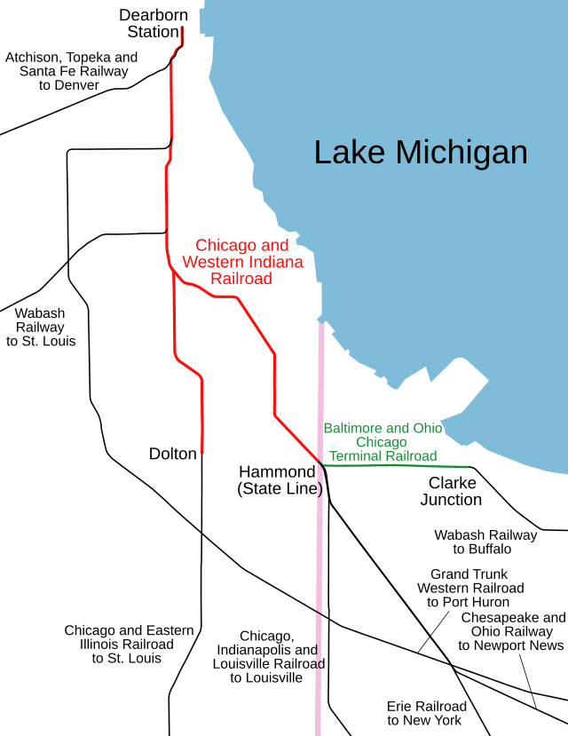
Bill Molony posted
This map shows (in red) the lines of the Chicago & Western Indiana Railroad Company, and its numerous connections, as they were in 1916, 100 years ago. 
At that time, the C&WI and Dearborn Station hosted the passenger trains of the following railroads:
Atchison, Topeka & Santa Fe
Chicago & Eastern Illinois
Chicago Indianapolis & Louisville
Chesapeake & Ohio of Indiana 
 Erie
Grand Trunk Western 
Wabash
Bill Molony reposted
Bill Nimmo at the ends of the orange i am trying to figure out what roads it leads into. hard to read the bottom one even if enlarge. the one of the right bottom looks like it goes into the nickel plate or the erie.
Bill Molony The line going straight south was the connection with the Chicago & Eastern Illinois at Dolton. The line to the lower right was the connection with the Wabash, the Erie, the Chicago, Indianapolis & Louisville and the Chesapeake & Ohio of Indiana at the Illinois-Indiana state line.
Bill Molony reposted
This original map of the Chicago & Western Indiana Railroad is from 1917.
The C&WI was owned by the Chicago & Eastern Illinois, the Chicago, Indianapolis & Louisville [Monon], the Chicago & Erie, the Grand Trunk Western, and the Wabash, with each of the five companies owning 20 percent.Ean Kahn-Treras hmmmm is Hammond Junction the implied name for the 87th Street split between the two legs of the CWI, or something else? Hard to tell on the map exactly where they are referring to.Bob Lalich Hammond Junction was an interlocking where the line to Dolton split with the line to Hammond prior to elevation. The layout was drastically modified with the elevation project, after which the passenger tracks split at 81st St, and the freight tracks split at 80th St.Ean Kahn-Treras was the rock island ever at grade just to the north as well?David DaruszkaDavid and 3 others manage the membership, moderators, settings, and posts for Chicago Railroad Historians. Chicago track elevation timeline: https://www.chicagorailfan.com/elevate.html
Paul Petraitis commented on one of Bill's postings
Bob Lalich responded to Ean's question: "Was the rock island ever at grade just to the north as well?"
Yes, the CRI&P crossed C&WI/BRC at grade prior to elevation. Separating that crossing was a big part of this particular elevation project. Notice the connection, which came about during a short period when C&EI passenger trains used LaSalle St Station.
Paul Petraitis answered a question about the Indian Boundary Line on one of Bill's postings
One of the only land concessions the US won after the stalemate that was the War Of 1812...part of the Treaty of St. Louis (1815 ?) it was surveyed over the winter of 1817/1818 from the mouth of the Little Calumet River near 92nd St...it bisects Lake calumet, appears on the ground at 127th and Wentworth and further south as George Brenan Highway parallel to I-57 south of Blue Island. George Brenan was the Roseland area's first historian and a contributing member of the Illinois Historical Society...also our neighborhoods first high school principal. He published in 1918 "The Wonder Of The Dunes". This is the southern IBL, there's a north one too that starts 10 miles north of the Chicago River and winds its way SW as well bisecting Bolingbrook. Since it precedes Illinois statehood (1818) its on most legal property descriptions.
Bill Swislow posted two images.
1

2
Bill Swislow posted
Ian M Contreras: Huh. Interesting that they show the branch towards the former Grant Works in Cicero way up at the north end of the Belt as being BRC trackage. I had always assumed that was BOCT property.
Paul Arden: Not sure of the exact arrangements, but I believe the BRC had / maybe still has trackage rights to serve a couple of industries on the Cicero Branch. As late as 2000, occasionally, the BRC would ask to go down there (when I was a Dispatcher for CSX/BOCT). I think almost all the industries are gone now.

Bill Molony posted
Chicago & Illinois Western Railroad Alco HH660 end-cab switch engine #1.
This locomotive was powered by a McIntosh & Seymour 531-series 6-cylinder prime mover rated at 600 horsepower, and rode on Blunt trucks.


A tidbit from a posting concerning the C&WI after its route parallel to the NKP to the state line was abandoned:
Bob Lalich The former mainline to State Line Tower is still in place between 81st St and 110th St. It belongs to NS now. NS also shifted the ex-NKP main tracks to the former C&WI RoW between 130th St and Burnham.

Monday, March 30, 2015

First Generation Road Diesel Frames

Craigslist
These Craigslist pictures were shared on Facebook's Abandoned Rails Group. The FP7 carcus was being offered for free. The owner wanted it out of his backyard. Fortunately, cab units are generally in better shape and you don't normally see that they were basically bridge trusses on wheels. A Facebook comment provides the history:
Bryan Humphries It is Ex-Alaska #1541 FP7-A, built 12/53, build #19066. It is actually the final FP7 constructed, so you got that going for you.
 

Craigslist
Facebook
It had a major electrical fire in 1979-80.

Second generation diesels were road switchers that replaced the truss frames with a big slab of steel at the bottom that was reinforced with a couple of T-beams.

Saturday, March 28, 2015

Top 10 Railroad Innovations of the 20th Century

More innovations

The November, 2014 issue of Trains has an article excerpted from Chapter 12 of the 506-page book American Railroads: Decline and Renaissance in the Twentieth Century. The list by Robert E. Gallamore and John R. Meyer is:

  1. Diesel-electric locomotives
  2. Containerization
  3. Roller bearings in sealed journals
  4. Freight car scheduling --- using computers and a system wide view to determine and track freight car routes.
  5. Wireless radio-frequency applications --- Walkie-talkies are old news. But this technology is still being developed in the 21st century to support Positive Train Control (PTC). PTC was significantly delayed because the FCC wanted each of the needed 20,000 antennas to be individually certified!
  6. Welded rail and quality materials --- by "quality materials" they mean better steel. Welded rail was introduced in the 1990s. One issue was developing rails that were strong enough to withstand the stresses of expansion and contraction as the temperature changed. It is very important that welded rail be laid at a temperature that reflects the average annual temperature for the area.
  7. Centralized Traffic Control --- developed in the 1920s, this allowed many railroads to go from double-track to singe-track routes or to increase the capacity of double-tracks. But its adoption can be slow. The Brighton Park Crossing did not change from tower controlled manual semaphores to CTC until 2007. Not all railroads converted to single-track mainlines. BNSF/CB&Q uses CTC so that both of its mainline tracks can be run in either direction. I remember riding a westbound Amtrak on the left-hand track as we passed a west-bound freight that was running on the right-hand track. Between Aurora and Chicago, BNSF/CB&Q has three tracks that can be run in either direction. Normally, M1 (the north track) is westbound, M2 is bidirectional, and M3 is eastbound. But when they are doing track work or switching local industries, you will see exceptions to this.
  8. Advanced warning and protection devices at crossings --- in addition to adding gates to crossing guards, they site adding ditch lights to the locomotives.
  9. Microprocessors: on-board, track-side, and elsewhere --- having worked with computers for over 40 years, this one scares me. We had a saying: "it takes computers to really screw things up." And the new signalling equipment installed by BNSF in Downers Grove, IL is a case in point. I have never seen a false gate closing in over 30 years with the old equipment. I saw at least a dozen in just a few months with the new equipment. I have avoided rail fanning because of the cold weather and because I get upset every time I see the new signalling equipment fail. But when I walk to the library, I can't help but watch the gates. There was a false closing during each of my last two trips to the library.
  10. Automated classification yards; unit trains --- unfortunately, many unit trains still go through the Chicago-area because the railroads that went around Chicago, e.g. Indiana, Illinois, and Iowa, where torn up. And trains have become longer, which has made them even harder to get through Chicago.
To be fair, Chapter 12 in the book is titled "Advancing Technology for American Railroads." Trains Magazine should recognize that not all innovations are because of technology.

In terms of productivity, reducing crew size from 5 to 2 and allowing crews to work at least 8 hours (i.e. removing the 100-mile workday rule) must have had a significant impact on productivity. (The United Transportation Union just voted against, by a 5-1 margin, a BNSF proposal to change about half its trains to one-person crews after PTC is implemented .)

The 1980 Stagger Act removing regulation and rates developed to address, literally, horse and buggy era issues was probably the most important innovation --- it probably saved the industry. For example, it allowed the railroads to charge market based rates for intermodal traffic. The Santa Fe has three tiers of pricing: Z trains for as fast as possible, Q trains for almost as fast, but cheaper, and S trains for an economy service. It also allowed railroads to sell or abandon branches. Unfortunately, they didn't invent how to railbank right-of-ways until after many RoWs were abandoned. I assume that railbanking removes the need to write off property by significantly reducing the property tax of unused branches.

Since working safely many times reduces productivity, independent organizations to improve safety were developed. For example, you no longer see track side workers without hard hats and safety vests. Other examples of safety rulings are that "polling" cars was banned in 1970; employees are tested for drug usage, at least after they have been in an accident; and some railroads do not allow any electronic devices in the cab, including cell phones.

Another change is diesel exhaust emissions. It is not uncommon to see pictures from the 50s and 60s where a diesel is generating more black smoke than a steam locomotive would generate. (Steam locomotives normally don't "smoke." You see it in many railfan videos and pictures because the fireman deliberately adjusts the fire to create black smoke for the "photo runs." I saw one video where you could see the smoke being "turned on" near the beginning of the photo opportunity.) Unfortunately, the older diesels are moved to yard work. This concentrates the pollution in a urban area rather than spreading it out along the country side. The EPA finally did a study in the 21st century around Cicero yard and measured higher than normal particulate pollution. Higher than normal asthma attacks suffered by urban kids had already been documented. Increased asthma is what motivated the yard pollution study.

The safety and pollution changes do not increase productivity. In fact, they reduce it. For example, EMD has had to quit building engines in 2015 because they could not meet the Tier 4 emission standard.  Organizations to improve safety and pollution were needed when they were created. But when/how do we conclude that they have done their job and are no longer needed? I can confidently predict that the workers in these organizations themselves will not conclude that they are done and that they need to find other jobs.


Wednesday, March 25, 2015

MoW: Track Ballast Tamper and Stoneblower

(Update: near the end of a time-lapse video shows a tamper and ballast regulator along with a ballast dump train after the installation of some new track.)

Video at 12:32
After years of use, the track ballast (the rocks around the ties) settles and the tracks can become uneven. Or the tracks are straight until the wheels of a car passes over them and they "pump" up and down. That is, the ballast is no longer properly supporting the ties. Last year I could have walked down to the BNSF/CB&Q tracks close to my house and take a video of ties pumping as a train passed. But BNSF did track work last summer and, fortunately, I can no longer easily get a video of track pumping. One of the machines, a ballast tamper, is of interest because of the many hydraulic actuators it uses.
Video at 0:15
This video shows a single-tie tamper. At timestamp 0:12 note the carriage it pushes in front of it. This is a projector buggy [term comes from comments in a posting and verified by a manufacture's documentation] so that it can measure the heights of the rails. At 0:19 you see a gripper come down below the head of the track and raise the rail. And then the "fingers" that go into the ballast to shove some ballast under the tie, one tie at a time. 0:58 shows what you can see in the other scenes as well, a ballast regulator has already made a pass over the rail to shove ballast on top of the ties. At 1:06 we see the ballast regulator working on removing the unused ballast from the ties. 1:18 is a sequence of the gripper and fingers in action. You can see that the fingers go into the ballast, and then move towards each other to squeeze ballast under the tie. What is harder to see is that the fingers vibrate as they squeeze.
Video at 1:57
The actuator seen at 1:57 is probably a vibrator. And at the top of the vibrator is the hydraulic ram that squeezes the fingers together. Then in the overview shot, say 2:05, you can see that there would be a hydraulic ram that raises and lowers the finger carriage. You can also see that control of all of the hydraulic actuators and the movement of the vehicle forwards is controlled by a computer because the operator is just standing and looking for problems. Then at 2:22 we see the ballast regulator cleaning up the tracks.
Video at10:14
They had to close a road at the crossing and remove the road filler because the far rail dips so badly you can see the dip without needing a projector buggy.

A video of a unit that does three ties at a time with a movable carriage so that the unit itself advances in a continuous motion.

Video at 0:14
When the ballast tamper is in transport mode, the bars that push the target ahead of it are folded up and the target is carried instead of pushed.

Update:
Micky Cecil posted
[Sometimes you need some more ballast before you can bring in the tamper. Is the guy trying to see if it is bent sideways as well as down? Where is the hard hat and safety vest?]
Joe Dockrill posted
FYI for those that don't know what a tamper does or how it works:
Tamping tines pack the ballast under the sleeper to produce a stable sleeper bed.
Plasser & Theurer developed a mechanised technique for this purpose: the system of non-synchronous constant pressure tamping which in professional circles is regarded as pioneering and unequalled in quality. The tamping tines penetrate the ballast bed from above and compact the ballast under the sleeper with a squeezing movement. Two factors are decisive here. Firstly, all tamping tines work with the same pressure; and secondly, the tamping tines vibrate with the ideal frequency of exactly 35 Hz. This directional, linear vibration combined with the non-synchronous tine movement produces a homogeneously compacted ballast bed.
[It is a shame the group is closed because many of the comments were informative.]
Jdoc Jdoc shared
Fred Bain Humm... taken from the clamp frame looking back. Obviously a switch capable tamper.
Screenshot, -0:53
When I watched this video of a 3-tie moving carriage tamper, I wondered who/how someone is watching the tamping. Also, I don't know what the second machine does. If they are working on a commuter route, that would explain why they can get a MoW work window only at night.

In this screenshot, note the two wheels in the lower-left corner that catch the rail under its flange and lift it to the correct height. Also note the hoses in the upper-left for all of the hydraulic circuits that are needed to operate the machine.
Then I came across a posting of this video (-2:00) showing that the operator rides under the machine behind the carriage. Note that he has a camera screen in the upper middle so that he can make sure the flange wheel is doing its job of lifting the rail.
Dom Rosso posted two photos with the comment: "Our old 4x4 and the switch tamper that does most of its work nowadays."
1

2

David Brumley posted two photos with the comment: "Triple head plasser!"
1

2
(new window)

Then Jdoc posted this video with the comment "little mud spot tamping. not mine, 3X tamper. another exclusive video........." I don't know if this is a closeup of what is happening in the second unit or if this is the first unit used in a different (touch up) mode.

(new window)  (source1, source2)
Frederick Keys T32 prototype joe, there's a video of it working online. Harscos first tamper with a wire lifting system instead of the double barrel. [Unfortunately, I don't understand what "wire lifting" and "double barrel" means.]
Stan Sandstrom Clifford is correct regarding the wire lift and line. It also has Youngman Positive Dislacement workheads which were developed in Australia. This machine is likely either in New Zealand or Australia.
Damien Smith Stan Sandstrom this machines was built in the states but yes the heads are Australian designed.
Frederick Keys 32 tool continuous action, not quite a 09-32 but they've had a fair crack at it. [The UP Plasser American pictured above may be the 09-32 that he is referring to.]
[I don't see the telescoping projector buggy at one end that I associate with tampers.]


Evidently a stoneblower makes tampers obsolete even though fancier tampers are still being designed. American railroads like to brag about their innovative technologies (a recent example), yet they won't try a stoneblower.
(new window)   (source)
Fred Bain Quite the concept. Treat just the wounded and don't disturb the ballast.
Stan Sandstrom Its a great machine. Harsco sold a lot of them in the UK. Unfortunately no US Railroad would try one. Two reasons I heard were 1. Some customers thought it wouldn't work on heavy haul track 2. They are very expensive and Harsco management didn't want to build one as a demo unit and no railroad wanted to buy one without a long trial period before purchasing. Only harscos sales department knows for sure.
(April 2019 Update: Harsco still has an icon on their videos page, but it is also broke.

So I have to switch to a text and photo description. [HarscoRail-web]

PERFORMANCE:

  • Pneumatically injects ballast under the tie to achieve track position accuracy of 1.0 mm without disturbing the pre-existing compacted foundation
  • Track remains in position much longer than track maintained by traditional tamping methods
  • Track immediately opened at line speed after stoneblowing
  • Post maintenance record of quality immediately available
  • On-board crane loads machine completely with stone in less than one hour
Harsco Brochure
Harsco Brochure

Joe Dockrill shared
stoneblower, a different type of surfacing, minor surface deviation correction by injecting stones


Ram Busse posted four photos and a video.

Joe Dockrill shared
Phil Kirkland Fire suppression system failure?
Kyle Dunbar Runaway Cummings!! ðŸ˜‚
1

2

3

4


Tuesday, March 24, 2015

Hay Bale Gathering Attachment

Near the end of the video
After watching a video of my daughter's horse, You Tube offered a video of a tractor carrying 12 round bales of straw. The title of the video claims it is Case IH, the tractor, that is awesome. What is really awesome is the attachment. On the right is a still I extracted from near the end as it raised its last square bale. A posting concerning round bales and large square bales has been on my to do list for months. That posting will remain on my to-do list because I want to concentrate on the hydraulics of this attachment in this posting.


I started counting the different movements this attachment can make because each one requires at least one hydraulic ram. Below are the movements.
  • raise and lower the tines for transport to the field vs. field use: 6
  • raise and lower the rear "wings": 4
  • raise and lower the far front tine bar: 1
  • raise and lower the entire front attachment: this is done with the tractor's hitch
  • raise and lower the far rear wings bar: 1
  • raise and lower the near rear wings bar: 1
  • raise and lower the entire rear attachment: this is done with the tractor's hitch
And then it occurred to me that each of these movements would also require a separate hydraulic circuit!  Tractors are being built with more and more circuits, but the most I have seen in a tractor's specification is five. My first thought is that when you install this attachment, you also have to install a control panel with a lot of valves in the cab. But that would require a lot of hoses between the attachments and the cab.
Timestamp 3:56 of the video
I found a view where you can rather clearly see that there is only two hoses between the tractor and the front attachment. So there must be some sort of electrically activated set of valves in the front attachment that is controlled by a set of switches in the cab. I went back to the beginning and looked for a view showing the hoses to the rear attachment. I found two pairs of hoses.

Timestamp 0: 21
The tractor is controlling five circuits: two hitches and three hose pairs. And the tractor needs to be able to set the hose pair circuits at "always full on." The front attachment is then controlling three circuits --- two tines position and the front tine bar. The rear attachment has two controllers --- one for the near wings bar and another for the far wings bar. The near wing bar controller is managing four circuits --- two tines position and two wing position. The far wing bar controller is managing those same four circuits plus a circuit to raise and lower the wing bar itself.

When I visit farm equipment dealers, I'm going to have to look for attachments of this complexity in terms of the number of hydraulic circuits being controlled and verify they also have electric wires running between the cab and the attachment. I have yet to see electrically controlled hydraulic valves in person.

The You Tube comments for this video had the theme that a self-loading wagon would be a better solution. Issues raised with this solution were: ground compaction, complexity, and illegal to carry a load on the roads.

Update: a video of a method to stack big square bales six at a time. It makes a stack that is 3+3+3+2+1 that is then covered by plastic.

TrucksMedia at 11:50
A video of baling the big square bales. There is some footage of gathering the bales. A couple of seconds after he lowers the baler's pickup at 1:12, you can hear a couple of cycles of the plunger packing the hay into the bale. At 1:34, the tractor driver plugged the unit and you can hear the slip clutch not allowing the pickup to feed anymore hay. So he had to backup and work the plug through the machine. At least he did not have to get out of the cab and pull hay out of the machine to get it going again. The baler we used was too stupid to stop the pickup when under heavy load, it would just break the shear bolt. You not only had to stop and pull hay out, you had to replace the bolt. It was a big no-no to not slow down when the windrow was big to avoid a plug. At 2:42 it occurred to me that one advantage of no longer making tricycle tractors is that the tractor can run over the windrow and the baler pickup can be centered behind the tractor rather than offset to the right. That makes it a lot easier to leave a field and run the baler down a road. You can also hear the plunger in that clip as it processes the windrow. At 4:26 they start collecting the bales.
20141108 0155
The tractors move across the field a lot faster than we would in the 60s and 70s. Do the bigger tractor tires smooth out a rough field that effectively? I looked through some pictures I have taken at tractor dealers to confirm that I don't think they have added springs between the axle and frame. Furthermore, in the video the tires do not move with respect to the frame. Note the dust clouds behind the balers at 8:59. I was surprised when one of the extras hired to stack the small bales in the mow said he would rather work in the mow than load the wagon in the field because of the dust in the field. Hay mowing was really hot, hard work. I could not do it. I would help by unloading the hay from the wagon onto the elevator and driving the wagon back to the field to get a full wagon while the mow gang rested. Finally, at 9:37 they show how they stack the bales four high on the gathering attachment. It turns out to be rather low tech but would take some skill on the part of the driver.

Screenshot from a video posted by Ulku Koroglu
Another Update: Stacking big bales seems to be a ripe subject for innovation. I still can't get over how fast farm equipment moves on a field now days.
This thumbnail seems to be bogus. The video shows multiple approaches for picking up bales, but nothing this complex.