Sunday, December 31, 2017

1917 Market Street Bridge over Tennessee River in Chattanooga, TN

(Bridge Hunter, Historic Bridges, 3D Satellite)
Officially named the Chief John Ross Bridge because he started the first ferry service here in 1815 and  he led the Cherokee Nation west on the 'Trail of Tears.'.
Completed in 1917 and rehabilitated in 2006. [Bridge Hunter]

20171217,18 9085

Market Street and Walnut Street Bridges, Boston Public Library on Flickr, License: Creative Commons Attribution (CC BY)

Bridges Now and Then posted
Chattanooga, Tennessee's Market Street Bridge, seen during construction c. 1915. (No credit found/pinterest)

I was playing peek-a-boo with the sun during my visit to these bridges. The sun was hidden by clouds when I took these pictures from the riverfront walkway.
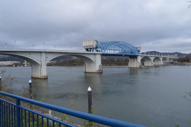


While I was taking pictures on the Walnut Street Bridge of truss details, I noticed the sun peaked out of the clouds to shine on the Market Street Bridge, but by the time I hustled over to the west side of the bridge to get a picture of the bascule spans, the sun was disappearing again.


I took a closeup view of the machinery on the south (left) pier, but later, when we were coming back across the the Walnut Street Bridge to the van, I noticed you can see the machinery better on the north pier because the bridge tower is not in the way. Thanks to the resolution of the camera, I can easily zoom in on the machinery part. It is nice that they painted the shaft of the pinion gear yellow because that makes it is easy to spot. It struck me that the rack was rather short. Then I noticed the round member that this Scherzer Rolling Bridge rocks back on was just a 45-degree arc or so. I'm used to seeing that round member in the Chicago area being  closer to a 90-degree arc.

Digitally Zoomed
Screenshot of Dawn Kropff catching the raising during an inspection
A smaller rolling member means that the bridge's raised position is far from straight up. Evidently, the only time it is raised is during its quarterly inspections. Even then, I can tell by the location of the pinion gear on the rack, they went only half way up the designed angle.
Excerpt from
screen shot

Image: TDOT, from Historic Bridges and WTVC
Jonathan Konopka posted
This is the Market Street Bridge in Chattanooga, Tennessee. It is a double-leaf bascule bridge that was built in 1917 and carries Market Street over the Tennessee River.

Douglas Butler posted
From Wikipedia Market Street Chief John Ross Bridge in Chattanooga, TN.

If it never is raised for boats, just for the quarterly inspections, then it really doesn't matter how high it goes.

(new window)


Below this photo of an interpretive sign, I have typed the text. Unlike many major projects, it appears construction continued on this bridge during WWI.

By 1911, load limits and costly repairs of the Walnut Street Bridge led officials to begin planning for a new bridge. Many officials and residents of Chattanooga wanted a Market Street Bridge because so much of the traffic crossing the river was destined for Market Street, the commercial center downtown. But officials also wanted a concrete bridge because maintenance would be easier. A Market Street location, then, was problematic in several ways. First, this location would destroy part of the wharf. Second, the level of the land at this location would dictate a low bridge, and the Army Corps of Engineers would only approve a bridge with channel spans 300' wide with 100' clearance because of the possibility that gunboats might have to travel the river. A concrete bridge would be unable to meet these requirements at Market Street without a drawbridge, and the necessary width of the spans also made the use of concrete unlikely.
Fortunately, the city's chief engineer, B. H. Davis, came up with a design that would please both the City Commissioners and the Army Corps of Engineers. the approved design was for a concrete bridge which would have the required 300' channel span, with shorter spans from the banks of the river to the central piers. In order to meet the federal height requirements, the central span would be a steel drawbridge of bascule design. This type of drawspan lifts, like one side of a see-saw, because of a counterweight. On the Market Street Bridge, each wing of the drawspan is conterbalanced by a block of concrete which moves toward the roadbed as it lifts the center of the span.
Construction began in late November 1914. The city issued $500,000 in 5%, 30-year bonds to finance the construction of the bridge, but as the engineers ran into more and more difficult problems, it became apparent that the bridge would cost far more.
The biggest problems arose because of the piers. In one site, an underground stream flowed into the cofferdam, preventing the concrete from drying; eventually the spring itself had to be plugged with concrete. Another site had, not a solid bottom, but a collection of large boulders. Caissons were built so that workmen called "sand hogs" could work underwater, excavating the boulders to reach bedrock. On top of their caisson rested a concrete pier 55 feet high, which weighed more than a million pounds. As their excavation moved closer to the bedrock, the pier moved down with them.
To build the concrete arches and the roadbed to span the piers, the contractor had to erect wooden falseworks. These were strong and fairly elaborate pieces of work, but they required constant attention because they prevented driftwood from passing. If left to accumulate, the driftwood formed an obstacle movable only with explosives. On December 19, 1916, a 28-foot flood caused driftwood to accumulate at a rate too fast to be controlled, and when the falseworks were dislodged by the pressure of the river, the span had to be abandoned because the concrete had not yet cured. The year of 1916 saw continued cost overruns and construction difficulties, and in March of 1917, the bridge faced another challenge. All of the masonry work was complete and work on the concrete counterweight had begun when the river again flooded, cresting on March 7 after reaching the fourth highest water level recorded in Cattanooga's history.The left inset photograph shows this flood as it appeared from Cameron Hill. The bridge, however, was largely undamaged, and work continued. The drawbridge was successfully tested on August 3, and on November 17, 1917, the bridge was officially opened and presented to the county. It was named to honor Chief John Ross, who led the Cherokee Nation west on the 'Trail of Tears.'
There was not as much pomp, nor were there as many attendees as there had been when the Walnut Street Bridge opened, but the bridge remains an engineering feat. Even though it cost twice as much as the county hoped it would, it remains the largest bridge of its type in the U.S., and the third largest in the world.
The inset photographs show some of the boats that traveled the Tennessee after the construction of Market Street Bridge. The Joe Wheeler was the last of the active steam packets, and in 1920, some of its parts were used to build the Captain Lyerly, which was used as a towboat. Towboats became the main type of commercial craft as the century progressed, and while this change took place, the engines changed as well. Diesel-powered engines pulled heavy loads faster and more efficiently than steamboats, and they were soon the only commercial boats on the river. The right inset is a U.S. gunboat, wharfed at Chattanooga during World War II.

A photo dump of the pictures I took while I walked towards and under the bridge along the riverside trail and then north and back south along the Walnut Street Bridge.


The beam of sun that was peeking through the clouds finally fell on the truss span. So I took pictures as a walked south on Walnut Street Bridge until the sun disappeared behind the clouds again.


Thursday, December 28, 2017

A Cut Stone Embankment Made with Some Coal?

(Satellite)
In towns like Joliet and Lemont that have outcroppings of dolostone, many buildings such as churches were made of cut stone. Even utilitarian structures such as embankments and bridge abutments and piers used cut stone.

20171217,18 9030
When we first approached a stairway that took us up from river level to the south side of the Walnut Street Bridge, it struck me that the stones in the embankment had a lot of coal soot still left on the stones. I've seen coal soot survive into the 21st Century. Here is a 2015 photo of an embankment along 18th Street in Chicago, IL, where the street goes under the Red Line. The elevated line above the embankment is the Orange Line.
20150513 1468
But the closer I looked at the stones, I decided some of them were not building stones covered with coal soot, but they were cut coal.

I took an overview of the stairwell and embankment from the bridge. That is our van, but you have to walk to the right to get to the walkway that takes you down to this stairwell. That walkway also goes under this parking area to the river so that you can get to the riverwalk without having to cross the busy Riverfront Parkway.

Obviously, this is a view down the stairwell on our way back to the van.
I took a closeup to confirm this is a black stone, not a normal building stone covered with black soot.
And then I saw these that look even more like coal.
An overview that catches the thickness of the wall.


Wednesday, December 27, 2017

NYC water supply: 1905 Croton Dam and Spillway Bridge

(Bridge Hunter, no Historic Bridges, HAER; B&T; see below for satellite information)

This dam replaced the original Croton Dam.

There is also a Croton Dam in Michigan.
This is another example of a dam using a tumble bay in its emergency spillway.
The 1894 pin-connected Quaker Road Bridge is just a little downstream from here.

According to Bridge Hunter comments, the 2005 bridge had to be rehabilitated in 2011. And then because of 9/11 arguments, it was closed to traffic. It is now for pedestrians and bikes.
3D Satellite
3D Satellite

Thomas Engel posted three photos with the comment:
The Croton Dam Spillway in New York State has had three, open spandrel steel arch bridges, 1905, 1976 and the current one shown in the first photo, 2005. Shortly before the construction of the latest, we did some inspection and evaluation of the 1976 version. The last step off that ladder is 200'.
1

2

3
Jeremy John Gibson Brown And the purpose of the ladder is?
Thomas Engel You get on the inspection scaffolding by going over the side on that ladder and taking a sideways step. The wire supported scaffold in visible in the second photo. The ladder was also used to enter the "spider" basket, as in the third photo.
Thomas Engel commented on his posting
The original span under construction. The rebuilding in 2005 was faithful to the initial concept.

Mark Gereg posted
Croton New York, in Westchester county
Peter A. Greenberg: The bridge is part of the New Croton Dam, completed in 1906. It is part of the oldest of New York City's 3 water supply systems. The dam and bridge combo carried automobile traffic until 2001. Today it carries pedestrians only.

1 of 5 photos posted by Bridges & Tunnels
The construction of the New Croton Dam in Westchester County, New York, necessitated the erection of two distinctive steel arch structures: a steel arch structure over the spillway and another over the Croton River. The spillway bridge was initially constructed by the Baltimore Bridge Company but was replaced in 1975 with a simpler arch design built of Corten steel due to deterioration resulting from exposure to roadway salt and spillway spray. Seismic capacity, deck-bearing details, and anchorage at the arch bases were among the design and structural issues that compounded the bridge’s deterioration, leading to its emergency closure in 2003 and replacement in 2005.
➤ Check out our latest Journal entry, "Croton Dam and Bridges," at http://bridgestunnels.com/2023/02/21/croton-dam-and-bridges/

This is the New Croton Dam which was built between 1892 and 1906. It is not obvious that the Theodore Roosevelt Dam is a masonry dam. But you can easily see the cut stones in this masonry dam. The Old Croton Dam was completed in 1842.

As I suspected, it is part of the water supply complex for New York City.
At the time of its completion, it was the tallest dam in the world.[5] New Croton Dam impounds up to 19 billion US gallons (72,000,000 m3) of water, a small fraction of the New York City water system's total storage capacity of 580 billion US gallons (2.2×10⁹ m3).[6][Wikipedia]

Cristian Opazo caught the spillway in use, License: Creative Commons Attribution-Share-Alike (CC BY-SA)

Underestimated Arsenal posted
"A parsimonious makeshift" is what three engineers called the plan for the south end of New York's New Croton Dam, in a report to the city's Croton Aqueduct Commissioners dated 18 November 1901.
The dam was still going up in the Croton valley in Westchester County. Its plan had three parts. A spillway along the rocky north hillside. A great stone dam across the valley. And at the south end, an earth embankment with a masonry core wall running down through its middle to the rock.
That last part, the board wrote, had been chosen "solely from economical considerations." Set beside the stone wall and "the massive spillway at the northern end," it would look out of place. They wanted "a massive homogeneous structure for the whole length of the dam."
This photograph shows how that argument ended. It was taken from the air in May 1931. The stone wall runs across the gorge from the spillway on the left, where water pours down the steps under the steel arch bridge, to the gatehouse on the right. The right-hand stretch of that wall was meant to be earth.
The man who started the change was W. R. Hill. He became chief engineer on 1 January 1900, taking over from Alphonse Fteley, who had designed the dam and run the work since 1892. By then the core wall was built, except for one stretch about 60 feet short of its full height.
In the spring of 1901, Hill's attention was called to cracks in that wall. But he said the cracks were not his real worry. His report of 15 May put it this way: "Even though there were no cracks, I consider that it would be unwise to complete the structure under the present plan, as I consider it would be an experiment."
He asked for three outside engineers to judge it. The commissioners named J. James R. Croes of New York, Edwin F. Smith of Philadelphia and Elnathan Sweet of Albany. They agreed with Hill, and on 16 April 1902 the commissioners adopted their recommendation.
So the half-built bank had to come out. In May 1902 the crews began tearing it down, and by March 1903 they had reached the base of the core wall.
Then the stone dam was carried on southward, but not in the old way. The older wall was rubble masonry, laid stone by stone. The new stretch was cyclopean concrete: large quarry stones bedded in wet concrete, with more concrete packed between them, about half of it concrete by bulk. It went in much faster. For part of the time the work ran day and night, and in August 1904 about 16,000 cubic yards were placed in a single month. Above the backfill, it got the same facing stone as everything else.
Not everyone thought it was needed.
Charles S. Gowen had been the resident engineer on the dam from its very start. In a paper to the American Society of Civil Engineers in 1906, he wrote that the city had spent nearly $1,000,000 it did not need to, and lost at least two years. Hill answered him in the same volume.
One small piece of the old idea did survive. Beyond the gatehouse at the far right, a short earth bank still finishes the dam, 145 feet long and only 26 feet high at most.
The last stone was laid on 17 January 1906. Today the dam stands over Croton Gorge Park, 97 acres at its foot, and footpaths climb its sides to the top.

"I know that I am absolutely right," W. R. Hill wrote to the Aqueduct Commissioners in May 1901. In the very same sentence, he asked them to call in three other engineers to check his judgment.
That is the part of this story I like best. The chief engineer was sure, and still he wanted the board. The board agreed with him, and so did two more engineers Mayor Low asked separately, William H. Burr of Columbia University and Nelson P. Lewis, the city's chief engineer of the Board of Estimate and Apportionment.
The other side deserves its say too. Charles S. Gowen, who ran the work on the ground from the first day, did not agree. He wrote that the core wall "stood for several years, showing no signs of settlement," and that the cracks near its top came from changes in temperature, and possibly some shrinkage of the setting mortar. Hill disagreed. He said five cracks within 100 feet were too close together for that, and that his case rested on the plan, not the cracks. Both men put their reasons in print in the Transactions of the American Society of Civil Engineers, volume 56, in 1906. I have not taken a side in the post, because the engineers of the day did not settle it either.
Where the numbers come from: The five cracks, five (5) in all, are Hill's own count, in his reply to Gowen in that volume: "five slight cracks in the core-wall, all within a distance of 100 ft." The 16 April 1902 decision, the cyclopean concrete, the 16,000 cubic yards in August 1904, the 145-foot earth bank and the last stone on 17 January 1906 are from Edward Wegmann's account of the finished dam in Engineering News, 4 October 1906. The "parsimonious makeshift" verdict and the board's names are from the board's report as printed in Engineering News on 28 November 1901.
The men who built it rarely get named in these papers. Wegmann gives the size of the force instead: at most 851 men on the masonry work, 475 on the dam itself and 376 in the quarry that cut its stone. At the height of the job the contractors had about 1,564 men on the whole contract, which also took in 21 miles of new roads.
About the photo. It was taken from the air by Captain A. W. Stevens of the U.S. Army in May 1931, and the print is held by the National Archives in the Army Air Forces "Airscapes" series. The note typed on the mount says the original negative had deteriorated by 1957, when the print was copied again. I have cropped away the mount and its typed label and turned the slightly warm print to plain greyscale. Nothing else was changed.
One honest limit: the photo cannot show you where the old wall ends and the newer stretch begins. That is the point of the facing stone. Wegmann's words for it were "like the rest of the dam."
Alon Dominitz: Wegmann's book is the Bible of early dam engineering but I didn't know about the public argument in the papers. Fascinating history and the final design resulted in one of the most beautiful dams in the nation.
It is first in the US Army Corps of Engineers video about the nation's dams.

Joel Kramer commented on the above post

Joel Kramer commented on the above post

Christopher R Hernandez posted six photos with the comment: "Croton Gorge Park Bridge, base of New Croton Dam, Croton on Hudson,  Westchester County, New York.  Completed 1906."
1

2

3

4

5

6

Steven Michael Rashkin commented on Christopher's post

Steven Michael Rashkin commented on Christopher's post

Steven Michael Rashkin commented on Christopher's post

Christopher R Hernandez nullposted six photos with the comment: "New Croton Dam Spillway Bridge, Croton on Hudson, Westchester, NY.  Original steel arch bridge was opened in 1905, then replaced in 1975 and replaced with the current bridge in 2005."
1

2

3

4

5

6

Thomas Engel commented on Photo 3
Same view of the 1975 version of the bridge, during an inspection we did in 2002.

William Patrick Still commented on Photo 4
Facebook Reel

Facebook Reel

They must have had a lot of rain in Mar 2026 because I'm seeing quite a few videos of water going over the spillway.
Facebook Reel