 |
| Bureau of Reclamation posted Hydropower is a renewable energy source that supports the nation’s energy independence. It provides flexibility that helps stabilize the electrical grid by supplying or storing electricity to meet real-time demand. Hydropower responds quickly after outages, helps meet peak demand and maintains proper voltage and frequency across the grid. |
 |
| Historic Photographs posted On this day (March 1st 1936) the Hoover dam was finally completed becoming the largest concrete arch dam. https://rarehistoricalphotos.com/building-hoover-dam/ DeWayne Ruggles: If I remember correctly they pumped cold water throughout pipes that went up and down the length of the dam to get the concrete to set. Then after the mass of the concrete had set they filled the pipes with concrete.. |
 |
| Today USA posted The Hoover Dam before it was filled with water in 1936. Do You Know posted Before it was filled with water in 1936, the back of the Hoover Dam presented a striking image of engineering prowess and desert landscape. The immense concrete structure stood prominently against the backdrop of the Colorado River and rugged canyon walls. Construction details, including intricate spillways and intake towers, showcased the ambitious vision behind one of America's greatest infrastructure projects. The barren surroundings emphasized the contrast between human achievement and the natural environment, highlighting the transformative impact of the dam on both the landscape and regional water management. This view captured a pivotal moment in the dam's construction history, foreshadowing its future role in water storage and electricity generation for the Southwest. Jesse Tillman: Most people don't realize that the cement is still hardening to this day. Because, when pouring the cement, so much heat was generated that chilled water lines were installed through the dam, and those chilled water lines are still removing heat being generated inside the dam. Ed Stutzman: Jesse Tillman yes I read it’s still curing after all these years ? Interesting Historic Heirlooms posted The rarely-seen upstream face of the Hoover Dam, Arizona side, nearing the end of its construction in 1935, the year it was dedicated. Construction of the Hoover Dam was finally completed in 1936. |
 |
| Steve Shorr commented on the "Do You Know" post |
 |
| Steve Shorr commented on his comment In 1982 [1983 is when there was so much water it went over the top.] |
 |
| D And G Adventure posted The construction of the Hoover Dam, previously named the Boulder Dam, was implemented to resolve flooding along the Colorado River. This image was taken in 1931, before the start of the construction project. Gary Goodpaster: It was originally called Hoover Dam after President Hubert Hoover. The Roosevelt administration changed the name to Boulder Dam in spite. In 1947 congress changed the name back to the original “Hoover Dam”. The more you know! |
 |
| Neha posted [The description sounds like AI generated platitudes.] |
 |
| History pictures posted [The description sounds like AI generated platitudes.] |
 |
| Bureau of Reclamation posted Check out this amazing photo from 1934 at The Hoover Dam worksite! You’re looking at a major moment in history—crews were hard at work building both the dam and the intake towers at the same time. On the left, workers were preparing to place the three millionth cubic yard of concrete. Incredible! |
 |
| Bureau of Reclamation posted During the construction of The Hoover Dam, engineers faced a major challenge: how to cool the massive concrete placements fast enough to prevent shrinking and cracking. Without artificial cooling, it would’ve taken more than a century for the heat from the curing concrete to dissipate! ❄️ The solution: Build the dam in pier-like blocks and circulate ice-cold water through embedded pipes. As each block cooled and contracted, crews pumped cement grout into the gaps—ultimately creating a seamless, monolithic structure. |
 |
| Ancient Threads posted The Hoover Dam, known at the time as the Boulder Dam, during construction, 1936. |
 |
| Colorado River Basin posted This historic engineering image shows a view of concrete handling at the upstream face of Hoover Dam. The crane at the base of the Nevada intake tower is busy at work, with a transfer platform positioned against the dam. Buckets are being expertly managed by the crane from the railway trestle below at an elevation of 720 feet. |
 |
| Bureau of Reclamation posted 🏗️ A Testament to American Ingenuity! 🏗️ The magnificent Hoover Dam was constructed using interlocking concrete blocks. During the height of its construction, our dedicated workers were lowering concrete buckets every 78 seconds! With each pour, they raised the blocks by six inches, demonstrating the incredible spirit of teamwork and determination that defines our great nation. This engineering marvel stands as a proud symbol of what we can achieve together! Bill Ciocci: One of the main things used to cure the concrete in the Hoover Dam was a system of cooling pipes embedded within the concrete blocks. Here's how it worked: 1. Embedded Pipes: A network of 582 miles of one-inch steel pipes was woven through the concrete blocks. 2. Water Circulation: Initially, cool water from the Colorado River was circulated through these pipes. 3. Refrigeration Plant: Later, a refrigeration plant, capable of producing 1,000 tons of ice per day, was established to chill the water, providing a more efficient cooling mechanism. 4. Heat Absorption: The cold water circulated through the pipes, absorbing the heat generated by the setting concrete and carrying it away. 5. Controlled Curing: This allowed the concrete to cool in a controlled manner, speeding up the curing process significantly. The result was a remarkable feat of engineering that enabled the construction of the Hoover Dam in a relatively short period while ensuring the structural integrity of the massive concrete structure. According to the Bureau of Reclamation |
 |
| The Hoover Dam posted Behold one of the most iconic sights from the construction of the Hoover Dam: a massive 20-ton concrete bucket suspended mid-air, delivering its 8 cubic yards of concrete with precision. These towering steel buckets—7 feet tall and nearly 7 feet wide—were filled at concrete plants on the Nevada side and transported by rail before being hoisted by aerial cableways to their exact placement. [For reference, a modern rear-unload ready-mix truck holds 9 yards. So each bucket is almost a truck load.] |
 |
| Dave Gunderson commented on Bill's comment Here's a picture of the cooling plant (the dark structure) that was located on the downstream cofferdam. It was the largest refrigeration plant in the world at the time. |
 |
| Science Professor Jim Caffey posted Hoover Dam under constructions, Feb 1, 1935. A testament to human ingenuity! this colossal structure not only tamed the Colorado River but was also built under budget at $49 million [$1,096,639,633 adjusted for inflation], showcasing America’s resilience and innovation during the Great Depression. Completed in 1936 |
 |
| The Hoover Dam posted Ever wondered what lies beneath the intake towers of the Hoover Dam? Check out this incredible view from the Nevada side, capturing the construction stage in 1934. The top concrete forms of the dam are reaching an impressive elevation of 1,170 feet [357m], showcasing the monumental effort that went into creating this engineering marvel. |
 |
| Hoover Dam posted On this day in history, March 26, 1935, we witnessed a milestone in Hoover Dam's engineering history! The four intake towers were nearing completion, standing proud just under 400 feet high and rising above the dam crest. These impressive structures symbolize the hard work and dedication that went into this incredible project. Here’s to the visionaries of the past who built the foundations for our future! |
 |
| CH Inam UL Haq posted The rarely seen back of the Hoover Dam before it was filled with water, 1936. Ellis Cleveland Ellis: This is a mirror image. Patrick Thinnes: Took about 6 years to fill. Pressure on canyon walls caused tremors in nearby communities. Edge McDermott: The penstocks were manufactured by Babcock & Wilcox on site !!!!💪 David Walden: Edge McDermott If I correctly remember, the penstocks were 30’ in diameter and the thickness of the steel was 3”! |
 |
| Historic Photographs posted A Turbine in the Hoover Dam, 1933. https://rarehistoricalphotos.com/building-hoover-dam/ Brett Wanamaker shared Josh Hansen: One of our customers has their business located in the Allis Chalmers hall that has the reinforced test room used to test the ones they made at AC. Huge! |
 |
| The Hoover Dam posted Just a casual conversation atop a stainless steel turbine runner weighing in at 62,000 lbs. and 15 ft. across. NBD. Besides the impressive bravery of these men taking a daring ride, the 150 ton cableway seen here deserves recognition for being the workhorse at Hoover Dam and still being in use today. Thomas Marty: What kind of turbine is that, doesn’t quite look like a Francis Wheel, obviously it is a High Head type of turbine. Sheril Helton: Thomas Marty that is a Francis turbine runner. Higher head Francis turbines have more narrow inlet opening than those you’re used too. I was a machinist at Hoover Dam for 10 years. |
 |
| The Hoover Dam posted As the dam rose in height, there had to be two concrete mixing plants. The Lo-Mix plant and the Hi-Mix plant. Here’s a general view of the Hi-Mix and Cement Blending Plants at Hoover Dam. This facility played a crucial role in the dam's construction by mixing the concrete needed for this monumental project. The plant features an unloading track and aggregate bins positioned above, where essential materials are stored before being mixed. The precise blending of sand, gravel, water, and cement was vital for creating the strong concrete that makes up the dam. Stay tuned for more insights into the incredible construction techniques that went into building this iconic landmark! Raymond Barr: Back in those days, the cement was delivered in individual bags in box cars because the enclosed cement hopper car wasn't available yet. |
 |
| Rick Freeman commented on the above post |
 |
| The Hoover Dam posted Concrete for the Hoover Dam was mixed in two different locations in order to keep up with the growing height of the dam. Here we see the Lo-Mix Concrete plant area, where railroad engines transported rock and sand from the staging area around the mountain to the work site. The materials traveled up the incline via the conveyor belt to the mixing house. Inside the mixing house, the black structure at the center, the rock and sand were combined before being loaded into concrete buckets on railroad flatcars. |
 |
| Explore USA posted The Hoover Dam at Lake Mead and The Mike O'Callaghan–Pat Tillman Memorial Bridge arch bridge crossing the Colorado River from Nevada on the left to Arizona on the right. |
 |
| My America posted Spectacular photo of the Hoover Dam 📸: [instagram.com/danglasvegas] |
 |
| safe_image for 7 Things You Might Not Know About the Hoover Dam |
 |
| Facebook sponsored ad |
.jpg) |
| Michael Graves posted Hoover Dam Generators Brett Wanamaker shared |
 |
| Clay Ogles commented on Michael's post here is a color pic |
 |
| The Hoover Dam posted On this day, 83 years ago (July 11, 1942), the A-2 generator at Hoover Dam began operation! This generator, along with its 16 counterparts, generates approximately 4 billion kilowatt-hours of hydroelectric power annually, supplying electricity to over 1.3 million people across Nevada, Arizona, and California. With a total nameplate capacity of about 2,080 megawatts (MW), the Hoover Dam continues to be a vital source of clean energy. Brett Wanamaker shared |
 |
| The Hoover Dam posted The power installation at Hoover Dam was complete when N-8 went online, December 1, 1961. This amazing photo captures the installation crew preparing for final placement of the foundation concrete for the N-8 generator. With the completion of N-8, the installed generating capacity of Hoover Power Plant, including station service units, reached 1,334,800 kilowatts. Jerry L. King: Power capacity is already down by 60% because of the low lake level and less water pressure available to spin the turbines. Last year Hoover Dam produced 4 gigawatt hours of power. In 1984, when the lake was full, it produced more than 10 gigawatt hours of power. In addition, only 5 of the 17 generators have been upgraded to ones that can operate with low water pressure. If the lake drops by another 25 feet, the 12 old generators will have to be taken offline, further reducing generation capacity. André Hagers: What a nonsense. The contractor is about to pour concrete. The installation team is still on holiday. At best one has come over to see how things are going at the 8th attempt. |
 |
| Bryan Avison commented on the above post |
 |
| Bryan Avison commented on his comment |
 |
| HighestBridges, West turbine room. Image by Eric Sakowski / HighestBridges.com |
 |
| John Punter commented on a post |
 |
| Dennis Wright posted Toured Hoover Dam today and learned that Allis Chalmers made some of the turbines. He said they were all still 70% original parts. Alex Igielski: Allis Chalmers made turbine parts, P&H made the cranes, Allen Bradley the controls, lots of Milwaukee manufacturing in that room. David Dickmyer: My son works at Voith in York Pa. The old Allis Chalmers turbine plant. They rebuild a lot of the old AC turbines. Tim Brannon: Russia tried for years to put power plants in the Aswan High Dam across the Nile river. Egypt threw them out and Allis-Chalmers came in and engineered the power plant with turbines, generators and switchgear according to a brochure we saw somewhere, decades ago. Brian Watson: I’ve been in there too. Some of the generators are A-C, some are Westinghouse |
 |
| Daniel Demaske commented on Dennis' post Lucas Rabe: Daniel Demaske Yes, the originals have been replaced last 20 years or so. Still, very impressive!! |
 |
| Ed Sparks posted On the inside of Hoover Dam on the Nevada side... Kevin Smith: I was actually just on this tour a few days ago and asked one of the guides about the rails. He claimed they are still very occasionally used to move very heavy equipment and plant components in and out. These components are lowered from the top of the canyon via a cable system onto rail cars below, moved into and through the plants, and sometimes lifted back off of the rail cars via cranes within each of the two power plants. Multiple rails are visible outside of each plant below the dam as well. |
 |
| Donnie Pinnick commented on Ed's post Here's the view if you're standing on those tracks looking towards Arizona! They go straight through the maintenance shop (in the middle of the dam), and end in a similar curve in the Arizona side of the powerhouse. I spent a couple of weeks out there doing some contract work. I never saw anything on the rails, but there's a network of them throughout the powerhouse. They appear to be for carts for moving heavy items around. [He provided several more photos of the rail network.] |
 |
| Dave Gunderson posted Hoover Dam Control Room 1948. This room was located in the ‘Central Power House’ on the 8th floor. At this time, the Dam was not yet fully functional as the last generator was installed in the 60’s. I first saw this control room in 1992 and it looked very close to this photo (down to the lime green walls). The Control Room was completely redesigned in the early 90’s with modern controls and instrumentation. Interesting enough, we had to replace the original cabling that was fifty years old. The old wiring using rubber insulation that had gotten brittle over time. For a year and a half we were crawling all over the plant removing miles of cables in ancient conduits. The new control system was referred to as a Supervisory Control And Data Acquisition SCADA System. All run by Computers. Hoover Dam was an interesting place to work at. Daniel H. Nelson: In the 1990s before 9-11 I was lucky enough to have a retired engineer for a tour guide who took us clear down to the generators and they had one of the armatures out on a cradle as they were replacing the bearings for the first time since it was built it was huge with the shaft where the bearings went was 36 inches in diameter. It said built by Allis Chalmers Co.Dave Gunderson: Daniel H. Nelson the best comment of the thread 👍. The Units (Generator/Turbine) had personalities from one unit to another unit. This depended on available ‘Head’ for generation. Very complex. But explainable. Bobby Rockwell: I think they still take core samples to check on the curing. Richard Struve: After 911, all public power generation plants were required to sever any and all physical connections from their control systems to the Internet. This included their administrative connections. It is also normal to disallow any outside laptop or similar device from connecting to the control net. Company laptops which are weekly scanned, are the only programming device allowed to connect. The SCADA terminals, being part of the control net, are not allowed external access. To clarify a bit, the SCADA computers are only the operator interface and data collection part. Programmable Logic Controllers, and/or Distributable Control Systems do the actual control. Typically, the systems will work without the SCADA computers. Richard T. Alamo: In the event of a power failure gates called stoplogs are automatically tripped to close and stop the flow of water through the generators, it's a pretty simple system, as long as gravity still works no worries. Djoko Soewarno: Sounds cool, so the generator itself how long it usually last? Before replace it with the new one? Dave Gunderson: Djoko Soewarno nothing lasts forever. We ALL have a life cycle. That includes turbines, valves, bearings and Generators. We went through an uprating process in the case of Hoover: 1.Generators were uprated (rewound) during the 90’s. 2.Wicket Gates in the Scroll Cages were replaced, allowing more water in. 3.Francis Turbines were redesigned and replaced for efficiency. This WAS the main enhancement. 4.SCADA was improved… |
 |
| This is one of several photos that are available in the comments. Given the "plates" on the left side, I wonder if they are working on the thrust bearing. [Update: Nope. They are rewinding the rotor and those are the metal sheets that are stacked up to build the armature.] |
%20At%20The%20Controls%20_%20The%20first%20Generator%20to%20be%20placed%20into%20operation%20at%20Hoover.png) |
| Comments on a post |
 |
| Someone commented on Dave's post that they would like a photo of the modern control room. This was his reply Ray Vaughan: When this went down, was there a back up system with actual meters and controls elsewhere? Dave Gunderson: Ray Vaughan there were secondary protocols in place using the primary instruments. I also designed a secondary system to monitor the flow and levels of the water. Thanks for asking. Alan Chris Heasley: Dave Gunderson who's SCADA software was used? What was used as the control platform? Just retired after 50 years in Automation and Process Control. Love picts like this... Dave Gunderson: Alan Chris Heasley the original SCADA system software was PC based and written in-house. The development software was done in VB6. We did use a commercial HMI for the operator screens (at the time it was called an MMI). Of course, the hardware lifecycle was met and it was redesigned with new hardware. Other improvements included smart relaying.The other improvements was going from copper RS-485 to fiber optic IP based comm. You understand. Good stuff… |
 |
| Dave Gunderson posted The Arizona Powerhouse wing at Hoover Dam. Brett Wanamaker shared |
 |
| Scottie Fogie commented on Brett's share I visited in 2018. |
 |
| The Hoover Dam posted The Hoover Dam's generators work on the same principles as an electromagnet. An electromagnet contains a magnet and wire coils separated by a small gap. As you turn the crank, the magnet spins near the coils, producing electricity. At Hoover, each generator has a turbine rather than a crank. Water striking the turbine causes the spinning that produces electricity. Imagine how much water power it takes to spin the turbine, shaft, and rotor with a combined weight of over 600 tons! |
 |
| David D. Webb commented on the above post This is the part that goes in that hole |
 |
| SparkTube commented on the above post Here we work with smaller stators but the principle is same. Mechanical ⚙️ energy into electrical energy. |
 |
| Jay rockwood commented on the above post |
 |
| Dave Gunderson posted The first Generator to be placed into operation at Hoover Dam happened in October 1936. This photo was taken to celebrate the occasion. If you look closely and have visited the Dam, you will recognize the area. It was taken in the Nevada Powerhouse. The spectators in the upper left deck is where the modern day tourists get to view the Generators. You probably looked down at this generator and didn’t know its importance. About the photo. The generator and it’s turbine are the round half wheels on the bottom of the photo. This generator is known as a ‘House Unit’ and provides power exclusively for the Dam’s use. The official designation of the generator is ‘N0’ Nevada Unit Zero. There is another unit in the Arizona Powerhouse called ‘A0’ that has the same functionality. It was probably the second generator installed at Hoover due to the significance of its mission. The other special attributes of these units are the turbines used to power them. They use a Pelton Turbine. The other generators at Hoover use Francis Turbines. Dave Gunderson: The primary concrete mix was perfected by Reclamation Engineer A.O. Patch and was called a ‘no fines mix’. The virtue of the mix being its resistance to shrinking as it dried. A modern expert on the subject was Dr David Moore who had spent time at the dam and was a subject matter expert on concrete.https://www.romanconcrete.com/docs/hooverdam/hooverdam.htm Bob Lieblein: The large shaft in the background is part of a Francis . Michael Lessick: Was that the Westinghouse side or the General Electric side ? If memory serves me right, that was how the contract was split up. |
3 of 44 photos posted by Linda Dougherty of the power plant tour. It includes a few photos of the tumble bay.
 |
| a |
 |
| b |
 |
| c |
 |
| Erik Nordberg updated This week's cover image celebrates the Boulder Dam, later called Hoover Dam, which began generating power on October 9, 1936. Photo from the Library of Congress |
 |
| Vero Loop posted By 1936, the Hoover Dam had risen to a height of 726 feet [221m], crafted from reinforced concrete in one of the most unforgiving canyons in the United States. Erected during the Great Depression, this colossal project spanned five years and served a purpose far beyond controlling the Colorado River; it reshaped America's perception of engineering. Initially named Boulder Dam, it generated electricity and water resources that spurred development throughout the Southwest. Innovative construction methods, extensive workforce management, and continuous work shifts expanded the limits of possibility in the 1930s |
 |
| The Hoover Dam posted The U.S. Construction Railroad didn’t stop at the canyon rim. Special spur tracks and a massive cable system lowered turbines, generators, and concrete buckets down to the dam’s power plant level. You can see the tracks on the left side of this photo. Three one-engine, one-car trains ran nearly nonstop to the Hi-Mix concrete plant, delivering the goods for the top 250 feet of the dam. That’s a lot of holiday hustle! Nevada State Railroad Museum, Boulder City: This photo is of the special visit by Union Pacific's M-10000 prototype streamliner in March 1934. The state-of-the-art passenger train was brought to the construction site as part of a publicity stunt corresponding with the installation of a large diameter pipe on the then Boulder Dam project. The museum has additional photos as well as artifacts from this visit in its collection. |
 |
| David Robertson commented on the above post From the Hoover Archives themselves, if anyone cares to look. |
 |
| Vintag eLas Vegas posted Rowing on Lake Mead, 1935. Early in '35 work on the dam was still underway. Water was rising on the new reservoir, months away from reaching the base of the intake towers. Composite photo created by Glenn A. Davis. |
 |
Vintage Las Vegas commented on their photo Davis' original photo, before the composite with a second image of a sunset sky. (James H. Down Jr. Photograph Collection, PH-00015, UNLV Special Collections.) |
 |
Vintage Las Vegas commented on their photo In April 1935, commercial boats operated by James Cashman were launched on Lake Mead. Water on Lake Mead did not rise to the base of the intake towers until June 1935. |
 |
Vintage Las Vegas commented on their photo 1938. The Bureau of Reclamation would have the water rise for several years and eventually test one of the two spillways on the sided of the dam. |
 |
| Robert Jackson commented on the above post Feb 1934 Colyton, old pictures posted [The description sounds like AI generated platitudes.] |
 |
| Robert Jackson commented on the above post Here's a shot of the dam being started in 1930. |
 |
| The Hoover Dam posted Check out this bird's-eye view from a high point near the future site of the highway bridge, which was constructed in 2010. The image showcases what will become the face of Hoover Dam, with the upper cofferdam visible in the distance, along with the Colorado River beyond. To the left center, you can spot the railroad trestle from above, featuring two sets of tracks that wind down from the tunnel inside the mountain. This trestle allows cranes to lift buckets of concrete mixed at a plant located on the opposite side of the mountain. The process involves picking up the buckets, transporting them to their dumping location, emptying them, and then returning the empty buckets to the flatcars for another load. |
 |
| Bureau of Reclamation posted Ever wonder what it looks like below the intake towers of The Hoover Dam? Check out this incredible view from the Nevada side, captured during construction in 1934. At this point, the top concrete forms of the dam had reached an impressive elevation of 1,170 feet. As we admire this engineering marvel, let’s celebrate the spirit of American history and the monumental effort behind one of the nation’s most iconic structures. Here’s to the visionaries and hard-working crews who made it all possible! |
 |
| The Hoover Dam posted Sure, toy trains circle Christmas trees—but the trains that helped build Hoover Dam were in a league of their own. 💪 The U.S. Construction Railroad was built to handle serious weight and terrain. Check out these specs: • 90-pound steel rails on untreated fir ties • 16–20 foot-wide roadbeds with a 6-inch gravel cushion • Tunnels up to 27 feet high and 18 feet wide • A 150-ton cableway to lower equipment nearly 700 feet • Locomotives weighing up to 65 tons, hauling 35,000 carloads over 31 years These weren’t just trains—they were the muscle behind a modern marvel. So next time you see a model locomotive under the tree, remember the real ones that helped light up the West. Edward Szarmach: Frances water wheel Greg Manwarren: Perhaps that is 3 years, not 31 ?? |
 |
| The Hoover Dam posted Flashback to a pivotal moment in the history of the Hoover Dam! Here’s a historic photo capturing the installation of the Z-Bank transformer on the roof of the Nevada wing of the powerplant. The installation of multiple transformers in a bank allows for increased capacity for the system, easier replacement of individual transformers in case of failure, and flexibility in load handling and distribution. The transformers at Hoover Dam play a crucial role in delivering reliable electricity to millions, showcasing the brilliance of innovation and teamwork at the Bureau of Reclamation. |
 |
| The Hoover Dam posted Who needs a boring commute when you can ride a concrete mixer down a canyon? Check out this historic photo of workers during the construction of the Hoover Dam! This four cubic yard capacity transit mixer was used to transport and mix concrete from a batching plant to the construction site, making it essential for this monumental project. The dam used over 3.25 million cubic yards of concrete; that's enough to build a 2-foot-wide sidewalk around the entire Earth! Kent Eaton: OSHA would have a heart attack! Thomas Marty: Kent Eaton we used to ride certain loads in the hydro electric plants that I worked at. That pretty much came to an end by 2020. [Is the guy in the back even hanging on?] |
Tumble Bays
I first encountered the term "Tumble Bay" in a comment by DanielG concerning the Croton Dam in Michigan. Some research has indicated two distinct uses of the term. One use is as a "splash bay" for the outfall from a Tainter gate. Another use is as the tapered receiving channel at the bottom of a long weir.
 |
| Vintage Las Vegas posted Hoover Dam's south spillway, August 1941. When Lake Mead first reached capacity, the 100 X 16-foot drum gates atop the Arizona-side spillway were partially lowered, beginning a testing of the spillway tunnels. The spillways on both sides of the dam were used again during the flooding of summer 1983. Here's the part of the dam we're seeing in this photo: https://imgur.com/dA0Wudf.jpg Photo from Southern California Edison Collection, Huntington Library. |
 |
| Vintage Las Vegas commented on Chris' comment I've seen the phrases "opening the spillway" which is totally incorrect, and "lowering the spillway" which is partially incorrect. The spillway is a fixed thing, it doesn't move. There are steel gates at the top of the spillway which can be moved. Here are two photos, with the gates up in the 90s, and down today. |
 |
| The Hoover Dam posted The Arizona spillway was placed in operation for the first time on August 6, 1941, soon after the reservoir level had reached a maximum elevation of 1220.44. The drum gates were raised for several hours on August 14, 1941, and a hurried inspection revealed that the tunnel lining was intact, and the inclined portion showed little or no signs of erosion at that time. |
 |
| Michael Graves posted Hoover Dam Spillway |
 |
| Michael Kerr commented on Michael's post The other side |
 |
| Nzl Chester posted Tourist's observe the overflow of the Hoover Dam Spillway on the Arizona side of the Dam July of 1983.This was only the second time in the Dam's history that the spillways had been opened. The first time was for a test. Image credit: Bob Riha (not my image) Robert Bauer: Spillway steel gates also had been raised to maximum height it was a sight I will always cherish the roar as well thrust of water exiting the tubes below the Damn was spectacular 👍 |
 |
| 5:00 video @ 0:49 |
 |
| @ 0:56 |
 |
| @ 1:50 |
A Google search showed only one dam outside of Michigan that used this design: Elkhart Hydro Dam. And that is close to Michigan and has the same geology of a deeply buried bedrock by sand, silt and clay.
For sites without rock bottom in reach, great care is necessary in defending the channel below from erosion. For such sites the "tumble-bay" dam is best adapted, in which the force of the falling water is dissipated within the confines of the structure. In dams of this type, the sheet of water is given a sheer fall, being well ventilated behind, into the pool or bay which has a depth of 1/2 to 2/3 the height of the fall, and the water escapes from the bay over a breast wall or roll-way with little or no destructive energy. [The Americanna]
 |
| Photo Cooke Hydroelectric Plant, Spillway, Cook Dam Road at Au Sable River, Oscoda, Iosco County, MI |
 |
| Photo Cooke Hydroelectric Plant, Spillway, Cook Dam Road at Au Sable River, Oscoda, Iosco County, MI |
 |
| mi0529data, p6 The tumble bay weir is 20' high and 12.5' thick at the base. p3 |
An important aspect of this tumble-bay design is a long apron downstream of the breast wall. You can easily see the long apron in this satellite view.
Jerry caught the middle gate open. It is open a small fraction of its total height, but it is making quite a splash over the breast wall. Robert also caught a gate open. Note the watermarks on the side wall. This gate had been making a big splash. Gary caught the middle gate open even wider.
I looked at the photos of the dams upstream from this one, but none of them caught water flowing through the spillway. But I noticed the Alcona Dam does not have a spillway. The Mio Dam has a single gate spillway and an emergency spillway.
(new window) The Richard B. Russel Project dam at 2:23 in this video also uses a tumble bay.
The other use of the term is for the tapered receiving channel along a spillway weir.
More terminology: some call the tumble bay the collecting trough and the downstream end of the trough empties into a chute. [ASCElibrary] Other terms are receiving and discharging channels. [core.ac.uk]
(Update: other example of dams using a tumble bay in their emergency spillway:
)
I've seen images of this usage of tumble bay when I researched Croton Dam, but now I can't find them. However, I remember that the spillways for the Hoover Dam have tumble bays. Now that I'm taking a closer look at them, I see the bay below the gates is deeper than the chute leading to the tunnel. In all other examples of a receiving channel that I have seen, the depth of the receiving channel is not lower than the discharging channel.
The depth of the receiving channel is tapered. It starts shallow at the end of the weir away from the discharge and slopes down to the depth of the discharge channel as it receives more water from the weir. (I spent some more time looking for some photos of a normal side-channel spillway for a plain earthen dam, but I still can't find any. I did find some neat photos for the Croton Dam, so those notes have been extensively updated.)
There are spillways on both the Arizona and Nevada sides. They were used in 1941 to test them and again in 1983 when there was a flood. The capacity of the spillways is high enough that they can cause flooding downstream.
The spillways use the outer (lower) tunnels. They are the second line of defense to avoid over topping the dam. The inner (upper) tunnels are running full bore because they are the first line of defense. They, along with the powerhouse penstocks, are fed by the intake towers.
(new window)
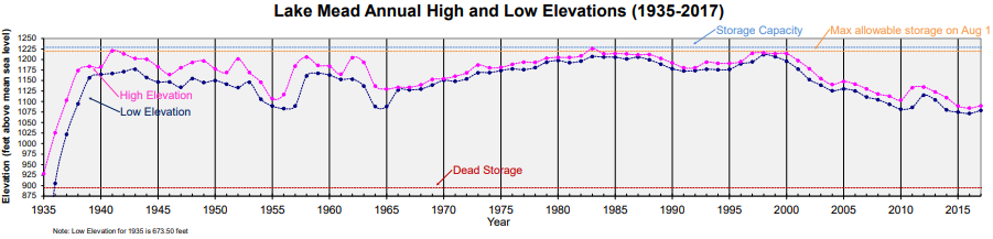
The fact that the Colorado River had been allocated over 100% of its flow has caught up with the government agencies. But no one seems willing to blink and reduce their take, so Lake Mead is being drained. (The variance before 1965 shows how the Glen Canyon Dam smooths out the river flow.)
The spillways are now high and dry. It will be a long time before they see water again, if ever.
At least the low water levels allow them to save maintenance on the spillway gates. It looks like they removed them.
 |
| Satellite |
I looked at the photos of the dams upstream from this one, but none of them caught water flowing through the spillway. But I noticed the Alcona Dam does not have a spillway. The Mio Dam has a single gate spillway and an emergency spillway.
 |
| Screenshot from the following video [Technically, this is probably a ski-jump spillway rather than a tumble bay. But this teaches me that part of the effectiveness of the ski-jump spillway is that it collects water at the bottom to help absorb the flow's energy.] |
The other use of the term is for the tapered receiving channel along a spillway weir.
 |
| Reservoirs in a Changing World: 12th Conference |
(Update: other example of dams using a tumble bay in their emergency spillway:
)
 |
| USBR-essays |
The depth of the receiving channel is tapered. It starts shallow at the end of the weir away from the discharge and slopes down to the depth of the discharge channel as it receives more water from the weir. (I spent some more time looking for some photos of a normal side-channel spillway for a plain earthen dam, but I still can't find any. I did find some neat photos for the Croton Dam, so those notes have been extensively updated.)
 |
| USBR-essays |
 |
| USBR-essays |
 |
| USBR-tnlfaqs, 1998 |
(new window)
 |
| Photo, Caption Water enters the Arizona spillway (left) during the 1983 floods. Lake Mead water level was 1,225.6 ft (373.6 m) |
 |
| USBR-lakemead |
 |
| 3D Satellite |
 |
| Screenshot "Because water levels are always low, turbines are now being replaced with more efficient ones that have a more favorable blade pitch to take advantage of less water pressure through the tunnels used for power generation." |
 |
| Kathleen's Window, Feb 2014 |
 |
| USlakes |
 |
| Forgotten Railways, Roads, and Places shared Dennis DeBruler http://mead.uslakes.info/level.asp K.a. Hughes Wonder how high the silt comes now? Dennis DeBruler I read that one reason they built the Glen Canyon Dam was to collect the silt so that Lake Mead doesn't fill up with dirt. |
 |
| History Daily posted Columns of the Hoover Dam being filled with concrete, 1934. The concrete was poured around the clock so it would knit together. There is awesome video in the Bell System film "It Couldn't be Done". They aren’t columns, they are blocks all poured separately, otherwise they generate too much heat ‘hydrating’. Concrete doesn’t ‘dry’, it hydrates and generates heat in the process. There are pipes with chilled water running through them to enable the chemical to happen slowly. Dr Carrier company provided the chillers. I wonder if the core has completely cooled yet? Steve Crippe not yetI saw the documentary “DamNation” and I highly recommend it for those of you interested in the daming of America It is currently low on water https://www.youtube.com/watch?v=ONBeT8j0UIg Armon Nicooneci The current level is at 1083 mean sea level or MSL. Which is good enough. If. it goes down, to 1075 MSL or lower, Arizona and Nevada is in big trouble.Railcars carried the fresh concrete for the dam in 4 by 8 cubic-yard buckets with overhead cableways lowering the concrete to the dam forms. During peak production, concrete buckets were delivered every 78 seconds. [Some comments have a snit over "pour" vs. "place" concrete.] Mike Breski shared Modern engineering has it 10 times over built.  There're 582 miles of one-inch pipe in the dam that carried cooling water for the blocks. After the blocks were cooled, they filled the pipes with concrete. I have heard that there is still concrete drying in the dam. Jim Munding all concrete continues to dry forever at a very slow rate.Historic Photographs posted Richard Barlow: It was built in 5 years 2 years ahead of schedule. In today's dollars it cost $750 million. That's about the same cost as one average Navy ship today. |
 |
This comment was part of the "pour" vs. "place" snit. |
How low can you go. This is when the lake first started filling up.
 |
| Vintage Las Vegas posted Lake Mead, April 1935. Recreation on the new lake began around this time. Rising water had not yet reached the base of the dam’s intake towers. Union Pacific Photo | Nevada State Museum, Ref: 0006:2019 |
 |
| Vintage Las Vegas commented on their post Feb. 1, 1935 (Photo: Water & Power Associates) |
 |
| Vintage Las Vegas commented on their post Undated, 1935. Hoover Dam close to completion. Water can already be seen at the base of the dam. (Photo: Water & Power Associates) |
 |
| The Hoover Dam posted On July 7, 1930, construction began on the #HooverDam. Built during the Depression, thousands of men and their families came to Black Canyon to build the dam. It took less than five years, in harsh conditions, to build the largest dam of its time. Now, years later, Hoover Dam still stands as a world-renowned structure. The dam is a National Historic Landmark and has been rated by the American Society of Civil Engineers as one of America's Seven Modern Civil Engineering Wonders. |
 |
| Vintage Las Vegas commented on their post The Arizona side spillway was tested in 1941. |
 |
| Historic Photographs posted Officials boldly ride in one of the penstock pipes of the soon-to-be-completed Hoover Dam (1935). Eileen Ilana Strauch: Amazing feat of engineering and construction. 4 billion kilowatt hours of hydroelectric power each year. Nary a whiff of greenhouse gases to boot. Bravo! Marie Hemstrom: These men were relatively safe. The 96 workers who died deserve remembering. Stephen Byrd: Dane Hansen - The modern construction hardhat was created during the Hoover Dam project...Men drilling into the cliff sides for explosives would wear cloth caps hardened with pitch to protect themselves from falling rock... Historic Photographs |
 |
| Bureau of Reclamation posted You’ll want to zoom in on this one! 🧐 This historic photo captures the pride and grit of American ingenuity as catwalks are installed on the upper portion of the downstream face of The Hoover Dam—a true symbol of our nation’s strength and energy leadership. Grout distribution pipes are strategically placed, with visible grout lines at elevations 1,025 and 1,075 feet, highlighting the meticulous craftsmanship behind this monumental project. Grouting played a vital role in both the construction and ongoing maintenance of the dam—filling gaps between concrete blocks, stabilizing the foundation, and sealing the cooling pipes within the concrete. A grout curtain was also installed to prevent water from seeping through the canyon rock and to reduce uplift pressure, helping ensure the dam’s integrity and longevity. This remarkable feat of engineering stands as a testament to what we can achieve when we come together to harness our natural resources and build a brighter future for all Americans. Mark Wilson: Did AI write this? I don’t believe this is very accurate, the referenced “grout pipes” were pipes used to cool the concrete and not to “seal” any cracks. Maybe the confusion exists because, after the concrete was done setting, the cooling pipes were abandoned in place and then filled with grout. Bureau of Reclamation: There is a tremendous amount of information on every single aspect of the history of the Hoover Dam from the conception of the idea, acquisition of political support and funding, construction, operations, and where it is today. Giving a comprehensive overview of any one aspect would be pages, and pages, and pages… and pages long. Our goal is to give enough information to spark curiosity, appreciation, and understanding of our projects and mission. We are humbled that serious history buffs and engineers take the time to read, reflect, and interact with us. Balancing the interests of the general public and industry insiders to create accessible social media posts for all audiences can be tricky. We are happy to provide supplemental information on posts we share. Let’s tackle some of these questions: Grout pipes? Perhaps semantics? When the concrete was first poured, river water was circulated through these pipes. Once the concrete had received a first initial cooling, chilled water from a refrigeration plant on the lower cofferdam was circulated through the coils to finish the cooling. As each block was cooled, the pipes of the cooling coils were cut off and pressure grouted at 300 pounds per square inch by pneumatic grout guns. Grouting was done using perforated pipes placed in every vertical and horizontal joint, and a three-row grout curtain was installed in the entire abutment, from rim to canyon rim. Concrete placement began in June 1933 and went steadily, averaging 6,000 cu yd per day, with grouting completed in June 1935. Grout Curtains? Sounds ominous. Don’t worry, it’s not. A specially designed joint was employed between the dam concrete and the rock abutments. These joints were not grouted prior to the reservoir filling because the designers believed the dam would deflect downstream under full reservoir load. A conventional grout curtain was installed beneath the dam’s upstream axis. This included a single line of holes 100 to 125 feet deep, about 14 to 21% of the dam height. An extensive program of post-construction grouting was carried out during the 1940s to extend a grout curtain beneath the Nevada spillway and intake towers. This program succeeded in mitigating the seepage problems that arose in 1937. Grout holes were extended to depths of 300 feet beneath the dam’s foundation, then pumped under pressure of full reservoir head. There is literally an entire paper on the grout curtain; check it out: https://web.mst.edu/.../hoover_dam/Rogers-HooverDam-Pt4.pdf [This .pdf has some construction photos.] Thank you for being an active part of our online community, what other topics interest you? We are here to nerd out with you. 🤓 |
 |
The Hoover Dam: Bureau of Reclamation *Opens door* Did someone say, "nerd out?" Here are some figure drawing from the link you shared that depict the progression of the grout curtain. 💁♀️ |
 |
| The Hoover Dam posted The men working inside the enormous 30-foot-diameter penstock serve as a striking reminder that, although we may seem small in comparison, we possess remarkable capability in the face of such monumental feats of engineering. These penstocks are essential for transporting water from Lake Mead to the turbines for hydroelectric power generation, designed to handle immense pressure for efficient and safe operation. The Hoover Dam stands as a testament to the ingenuity and dedication of those who built it. |
 |
| Bureau of Reclamation posted 🎄 Deck the halls? At Hoover dam we grout the walls! 🛠️ While most folks were stringing up tinsel, the builders of the Hoover Dam were busy with something a little more... cementitious. Enter the grouting jumbos; massive machines designed to drill into concrete tunnel linings and canyon rock. These beasts pumped pressurized cement grout into every nook and cranny to: • 🧱 Stabilize the canyon walls • 💧 Stop sneaky water seepage • 🔍 Fill in tiny cracks and hidden cavities It was this behind-the-scenes hero of the dam’s construction making sure everything stayed solid, sealed, and standing strong. Alan Ragsdale: This picture has nothing to do with the grouting to stabilize the canyon walls. That process was done twice when the workers prematurely stopped pumping grout into canyon wall cracks if it took too long (used too much grout). After filling the lake began, it was discovered that the grouting was insufficient and a very difficult and time consuming redo of canyon wall grouting had to be undertaken. Massive Re-grouting: From 1938 to 1947, crews worked from interior galleries in very tight quarters to drill holes much deeper (sometimes three or four times the original depth) to expand the grout curtain. |
 |
| The Hoover Dam posted This powerful 100-ton Marion Electric Shovel was hard at work excavating blasted rock from one of the diversion tunnels during the construction of Hoover Dam. Outfitted with a 3.5-cubic-yard dipper, this mechanical giant was ideal for scooping up large volumes of debris with each pass—perfect for the massive scale of the project. The Marion shovel was electrically powered, a cutting-edge feature at the time, allowing for more consistent and powerful operation compared to steam-powered predecessors. Its robust design and capacity made it a critical piece of equipment in one of the most ambitious engineering feats of the 20th century. This photo, taken by the Bureau of Reclamation in 1932, captures not just a machine, but a moment in history when American ingenuity and industrial might came together to reshape the West. [Some comments indicate that even with electric power for the shovels, they had to figure out how to ventilate the tunnel because of carbon monoxide from the trucks.] |
Jim Brown posted three photos with the comment:
The hoist room of the giant 300 ton (now 250 ton) Lidgerwood cableway at the Hoover Dam, which handled lowering all of the heavy powerhouse components down to the river level. The front drum has two sets of haul cable (most had one) that entered the top of the drum, made several wraps, then left the bottom. The top set travels all the way to the tail tower across the canyon, and is turned back on sheaves to the carriage. Turning the drum one way pulls the carriage towards the head tower, reversing pulls it away.
The two monster hoist drums connect to the same main block, and are kept synchronous by having only one layer of cable, requiring diameter and width to accommodate the needed length, always paying out or in at the exact same rate. This same concept is still used on monster shipyard Goliath cranes with multiple main blocks.
David Woll shared
Note the red spray bar on the left. That is probably doing more water than the fire hose.
The Hoover Dam posted four photos with the comment:
 |
| 1 |
 |
| 2 |
 |
| 3 |
July 19, 2022:
 |
| safe_image for Explosion at Hoover Dam [Video] "Video circulating on social media, apparently taken by a tourist, showed a small explosion and smoke and fire coming from the base of the dam, the largest in the United States and the source for a 2,080-megawatt hydroelectric plant, enough for about 1.3 million households. Update: Reuters is reporting that it was a transformer. That is good news if it wasn’t terrorism, though there have been no reports about the cause of the explosion yet." |
 |
| Screenshot from video in above linked article Note the red flames at the base of the smoke column. |
 |
| reuters ..Bureau of Reclamation/Handout via REUTERS |
The Hoover Dam posted four photos with the comment:
We’re excited to share that our talented hydroelectric mechanics have successfully lowered a nine-ton stop log using the powerful 250-ton cableway! These massive water barricades are essential for preventing tail bay water from flowing into the outlet pipes or draft tubes, enabling vital maintenance and repairs on our turbines.The operation started from the canyon rim, lowering the stop log hundreds of feet down to the powerhouse tailrace, where it was skillfully positioned by gantry cranes for the next maintenance season. This vital process ensures the continued efficiency and safe operation of Hoover Dam!📸 USBR / Christopher Clark
 |
| 1 |
 |
| 2 |
 |
| 3 |
 |
| 4 |
 |
| Colorado River Basin posted The Hoover Dam's generators work on the same principles as an electromagnet. An electromagnet contains a magnet and wire coils separated by a small gap. As you turn the crank, the magnet spins near the coils, producing electricity. At Hoover, each generator has a turbine rather than a crank. Water striking the turbine causes the spinning that produces electricity. Imagine how much water power it takes to spin the turbine, shaft, and rotor with a combined weight of over 600 tons! |
 |
| Dave Gunderson commented on the above post I remember some years ago (probably in the late 90’s), one of our managers gave a presentation to the stake holders about how Hoover operated. I’ll refer him as ‘Dan P’. It was a great presentation as Dan laid it all out in simple terms. What utterly impressed me was Dan took the time and energy in his Power Point to include hand drawings of how the Generators actually operated. I later asked Dan for a copy of his presentation which he was more than happy to share. As we are on the subject of how it works, I’m pretty sure that Dan wouldn’t object to them being shared here. |
 |
| Dave Gunderson commented on the above post |
 |
| Dave Gunderson commented on the above post |
 |
| Dave Gunderson commented on the above post |
 |
| Dave Gunderson commented on the above post |
 |
| The Hoover Dam posted 🎰 Roulette wheel? Not quite... this one always hits the jackpot! You're looking at Unit No. A8, a 55,000-horsepower turbine generator inside Hoover Dam. Its might look a bit like a roulette wheel, but instead of placing bets, it’s cranking out clean, renewable energy. Fueled by the mighty Colorado River, this powerhouse has been lighting up the Southwest since the 1930s—no luck required! Arthur Guilfoil Sr.: Turbine and scroll case. The generator would be above this with another shaft between them. Jerry L. King: Hoover Dam has 17 generators, only 5 of which have been replaced with units that can work with low water pressure. The current lake level is 1057 feet above sea level. If it drops another 22 feet to 1025 ft., the 12 old generators will have to be shut down. Even without that, the generating capacity of the dam is already down 60% from its peak because of the low lake level and less water pressure to spin the turbines. Last year Hoover Dam produced 4 gigawatt-hours of power. in 1984, when the lake was full, it produced more than 10 gigawatt-hours of power. |
 |
| The Hoover Dam posted Here is your winter driving safety driving reminder to check your tires! This photo shows the largest pneumatic tires manufactured (as of 1932), which were used on several of the trucks in operation at the Hoover Dam Project. In 1932, there were only 3 molds this big in existence. [I know that tractors started out with steel wheels, but I would have thought that rubber tractor tires would have been at least this big by 1932. Nope, Firestone and Allis-Chalmers partnered to install rubber tires on the Model U tractor. And A-C introduced the Model WC in 1933 as the first tractor to offer pneumatic rubber tires as standard. [AI Google search results for "when were rubber tractor tires invented"]] |
34:42 video describing its construction this link broke; so, was this 34:51 video essentially the same one?
I’m surprised that nobody has made a comment here after all your research. I’m more surprised that I’m making the first one…
ReplyDeleteNo doubt, you have questions. Yes. Worked there for 12 years. The only employee that physically wasn’t there as I was the ‘outside man’.
Worked Telecomm in the beginning. Later in SCADA. Did the remote Jack of all Trades stuff. Later, promoted to collect and distribute Data from the river (yeah, more specialized Telecomm).
About my posts: Boy was I ever shocked at how popular that topic was. Also shocked to see the abundance of experts crawling out of the woodwork.
Hoover was one of my favorite gigs while I worked. The places I got to see that NOBODY usually sees. So full of history too. You actually get to know the structure, the machinery - all having personalities.
You mention somewhere that Hoover was overbuilt. Absolutely true. Do a little research on the St Francis Dam and that will give you an answer. Also research the Engineer Frank Crowe to get a better understanding about Hoover’s construction. Fascinating history. Best, Dave