Sunday, October 31, 2021

1903,1972 NS/Pennsy Shocks Mills Bridge over Susquehanna River

(Bridge Hunter; no Historic Bridges; Satellite)

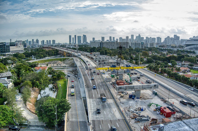
The steel girder spans in the middle are the repairs made for the July 2, 1972, flood damage caused by Hurricane Agnes.
D Blood, May 20221

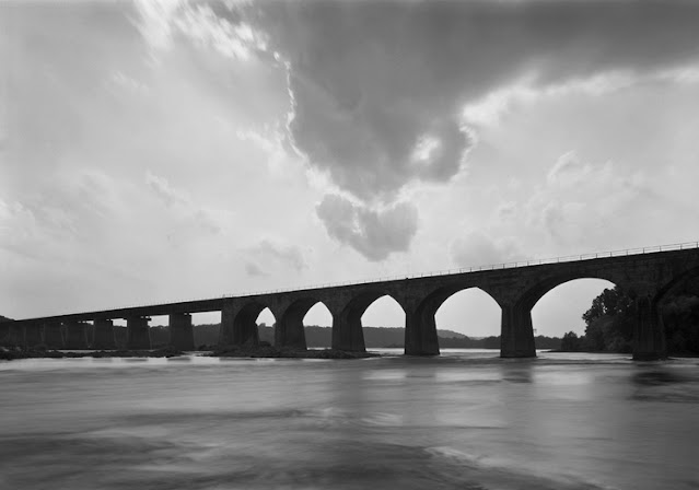
michaelfroio
"The 28 arch stone bridge was over 2200 feet long spanning the Susquehanna River with trains riding approximately 60 feet above low water."

safe_image for Jay Miller Flickr
Ray Brunner: The bridge was partially destroyed in the 1972 hurricane Agnes flood. Note the replacement spans.
Mike Froio: Ray one of the only major failures of a PRR stone arch bridge. From what I’ve read this bridge had issues well before Agnes. Even during construction Shocks Mills required additional shoring as the piers had issues.

The Pennsy Chief Engineer William H. Brown sure liked stone arch bridges. At first glance, I thought this was the Rockville Bridge. Fortunately, I read the comment and realized that this was a different bridge. "Until settling compromised a pier on the Rockville bridge in 1997 this [flood repair] would be the only major failure on record of the proven and sturdy construction methods Brown used during his 25 year tenure as Chief Engineer." [michaelfroio]

James Klyeman posted
Shocks mill bridge lancaster co. Pa
Rob Nichols: One of the best views I've ever seen of Shocks Mill bridge. Here we can see the deck girder spans at the opposite end that replaced the arches washed out by Hurricane Agnes in 1972. Further upstream at Harrisburg the river is wider so the flow wasn't as concentrated which allowed the Rockville and Reading bridges to survive. Sadly now NS is following the old Conrail policy of refusing to maintain Rockville bridge and assuring that it will fall apart.
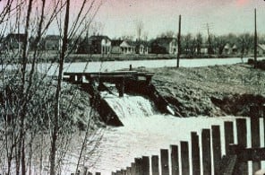
Photo via VisitPaDutchCountry, this site has several closeup photos of the bridge

William VanZee, Aug 2019

The walkway was opened Nov 1, 2014 and connects Brainbridge with Marietta. [SeanHeisey]
proveng

Metrotrails posted
Northwest Lancaster River Greenway passing b Shocks Mill Bridge over the Susquehanna River near Marietta Pa.
Completed in January 1905 for the Atglen and Susquehanna Branch of the Pennsylvania Railroad, the 2209 ft bridge originally encompassed 28 stone arches. It is often referred to as the Enola Low Grade Line.
In 1972, flooding from Hurricane Agnes destroyed 9 of the arches, which were replaced by 9 deck girder spans on concrete piers.
The bridge is still actively used by Norfolk Southern today, although South of Columbia, much of the branch is abandoned.

(new window, 1:00) Sean caught the river during a flood. Note that the walkway is covered by water.

Saturday, October 30, 2021

1965,1989 I-195 Bragda Bridge over Taunton River at Fall River, MA

(Bridge Hunter; no Historic Bridges; Satellite)

The Bragda Bridge is the cantilevered bridge in the background.
Street View

I tried getting a street view from the drawbridge in the foreground in the above image, but Google Maps would not switch to street view mode when I zoomed in. When I tried "driving" onto the bridge from Riverside Ave, I discovered that bridge is closed.
Street View

Bridges Now and Then posted
The Charles M. Braga Bridge over the Taunton River between the town of Somerset and the city of Fall River, Massachusetts. This photo would date between August 14, 1965, when USS Massachusetts was anchored at Battleship Cove, and opening day of the bridge, April 15, 1966. (Herald News Archives)

James Torgeson shared
Bethlehem Steel and US Steel meet at Fall River! The American Bridge Division of US Steel is building the Braga Bridge while the Bethlehem Quincy-built battleship USS Massachusetts (BB-59) looks on.

Jul 2016 Photo by Christopher Finigan via BridgeHunter

DeBruler


Friday, October 29, 2021

EJ&E Rockdale and Statesville Prison Branches

Rockdale North: (Satellite, was Rockdale Junction)
Rockdale South: (Satellite, now Joliet Junction Trail and it continued northeast past some industries)
Statesville: (Satellite, a tree line is what clued me in to research this)

Kevin Piper posted a history and some images of the EJ&E Branch that began in 1904 as the Rockdale, Joliet  & Lockport Terminal Railway. EJ&E discontinued service on the 6.46-mile line in 1991 because a wooden trestle was severely damaged by a fire. In 1994 the Joliet Junction Railroad was founded. After obtaining a $390,000 loan from the Illinois taxpayers, it gave up in 1999. "The line sold for $467,424 to the Forest Preserve District of Will County, which created a recreational trail, called the 'Joliet Junction Trail.'" I hope that $467,424 was used to pay off the loan.

Dennis DeBruler commented on Kevin's post
While looking at a satellite image of Rockdale Junction, I noticed there was a tree line curving northward as well as this branch going south. The 2005 SPV Map shows an EJ&E branch going up to Statesville Prison. This abandoned RR map shows both branches.

As expected, the prison has a boiler building. I presume it now burns natural gas instead of coal.
3D Satellite

But there is not evidence of an abandoned RoW in the prison.
Satellite

I think that is because the track ended just outside of the prison wall.
Global Earth, Mar 1994

They had structures at the wall to pass the coal through the wall. Remnants of the outside structures are still standing. The inside structure as been removed except for the foundation.
Satellite


Thursday, October 28, 2021

1882 Little Hoosac Tunnel in North Adams, MA

West Portal: (Satellite)
East Portal: (Satellite)

The Hoosac Tunnel is just a little east of this tunnel. This tunnel is 324' long. [JoshKellogg]

East Portal:


Nov 1979 Photo by Geoff Hubbs via BridgeHunter, License: Released into public domain

Ron Sherman posted
Would anyone know the location of this tunnel? Thanks.
Brian Burnett
Little Hoosac Tunnel, North Adams, MA


West Portal


The west portal is hidden by the street overpass for Mohawk Trail.
Jan 1979 Photo by Bruce Nelson via nerail

Location


Satellite


Wednesday, October 27, 2021

Columbia Lock and Dam on the Ouachita River near Columbia, LA

(Satellite)

I learned about this lock and dam because of these three posts.

Massman Construction Co. posted two photos on Dec 13, 2018, with the comment:
The Massman team is currently performing emergency repair work at the Columbia Lock and Dam in Columbia, Louisiana. Massman is partnering with the USACE’s Vicksburg District to address seepage, sand boils, and voids beneath portions of the structure. 
As a result of these issues, the lock and dam, as well as portions of the Ouachita River, have been closed to navigation since July 3.
1

2

Massman Construction Co. posted on July 23, 2020
Check out this story about our recent experience partnering with
Vicksburg District - USACE
to make emergency repairs to the Columbia Lock and Dam. Thanks for sharing,
The Waterways Journal
!

Massman Construction Co. posted on Oct 6, 2020
The Columbia Lock and Dam Emergency Seepage Repairs recently earned
Engineering News-Record
's Award of Merit in the Water/Environment category in Texas & Louisiana.
In the face of an “exponentially increasing risk of failure” of the lock structure due to foundational undermining, Massman partnered with
Vicksburg District - USACE
to perform emergency repairs to the structure and restore the Ouachita River’s navigability.
Congratulations to the project team!


Massman's project web page contains three photos with the comment:
The Columbia Lock and Dam is owned and operated by the United States Army Corps of Engineers’ Vicksburg District. In the face of an “exponentially increasing risk of failure” of the lock structure due to foundational undermining, the District declared an Official Dam Safety Emergency and suspended navigation through the lock in July 2018. We partnered with USACE to perform emergency repairs to the structure and restore the Ouachita River’s navigability, including the development of an alternative construction approach to address voids that were significantly larger than anticipated.
The project involved the drilling of nearly 300 holes ranging in diameter from 4 to 15 inches, subaqueous grouting and concrete placement, and the installation of a sheet pile cutoff wall. Other major scope elements included the removal and replacement of a portion of the lock floor without dewatering the structure, and the installation of a permanent relief well and dewatering system.
1

2

3


Tuesday, October 26, 2021

Auger Cast Piles or Continuous Flight Auger (CFA)

Some contractors working on the Miami Signature Bridge bragged about pioneering the use of "auger cast piles" for building bridges in the US. A comment by mkeit on those notes taught me that the technique is also called Continuous Flight Auger (CFA). Using many piles under a foundation has been the solution for many decades as to how to hold up heavy structures. Either the piles go down to bedrock or they are long enough to create enough friction to hold the structure. Initially, the piles were wood poles driven into the ground. Then H-beams and precast concrete columns were driven. But when the piles are really thick, they can't be driven. For thick piles, a hole is bored into the ground and then filled up with reinforced concrete. The drills I have seen have an auger with just a few turns on the end of a long shaft.
Screenshot

The auger is lowered into the bore and the shaft is turned until the auger fills up with material. Then the auger is brought up out of the bore, the unit turned to its side and the auger is spun to fling the material out of the auger. Then the cycle is repeated by placing the auger back into the bore. If the soil is not competent, then a steel casing has to first be driven into the ground to keep the soil from collapsing back into the bore being dug. Once the bore is dug, a rebar cage is lowered into it, and it is filled with concrete.

Continuous Flight Auger uses an auger that is a long as the desired depth of the bore and that has a hollow shaft. It allows drilling bores in incompetent soil without the need to first drive a casing into the soil. It also removes the dead time of raising the auger out of the hole every few feet to discard the material. Since a picture is worth a 1000 words, this video explains the process.
(new window, 1:57)


This video explains the process using real equipment.
(new window, 4:30)  (It is a shame that they play the torture music during the narration. In one case, it actually drowned out some of the words!)


Monday, October 25, 2021

Canal Overflow Weir

I've taken some photos of overflow weirs. But I don't have the time needed to try to find them. But I'll start these notes so that, if I come across a photo. it is easy to save it.

Canal Society of Indiana posted
For a canal to function properly, the engineers designed them to maintain a constant level of water of 4-5 feet depth. Normally the problem was getting enough water into the canal but like a modern bath tub you had to have a way for the excess water to be safely released. On the Wabash & Erie Canal at Defiance, Ohio a waste weir was built into the bank of the canal. Once the water level filled to the opening, excess could be safely directed into a nearby waterway.


Sunday, October 24, 2021

I-395 Miami Signature Bridge "The Fountain" and Midtown Exchange Rebuild

(Satellite)

(Update: RoadTraffic-Technology article  "Rising 325ft above the ground and spanning 650ft, the arch will be the world’s third-biggest precast concrete segmental arch." H&H has more photos.)

Rendering by Archer Western - De Moya via miami.curbed-2017

The above bridge over a park is part of a project that is rebuilding the Midtown exchange and adding lanes to the east/west route. It was estimated at $802m, but it is now up to $818m.
Satellite

In addition to rebuilding the existing roads, the project will add some FL-386 express lanes between NW 17th Ave and the MacArthur Causeway and it will make a 30 acre "community activity space" under the east end of I-395. They make that community activity space by hanging the new I-394 roadbed from cables. 30% of the design competition for the bridge is that it looks pretty.  (The 30 acre figure comes from a factsheetmiami.curbed-2017 provides a figure of 55 acres. RoadTraffic agrees with the 55-acre Heritage Trail figure.)

Before I dig into the Signature Bridge, I'll describe the FL-386 express lanes because it did not have a design controversy. A rendering makes it obvious that the express lanes are being built over the local lanes.
RoadTraffic and TheProject

The winning design for the Signature Bridge was announced in May 2017, and it was by Archer Western - De Moya. Using a tunnel to have an open park in the museum area of Miami was quickly ruled out as too expensive.
Rendering by Archer Western - De Moya via miami.curbed-2017, this article has several more renderings of the proposed bridge.

Below was the runner-up design by Fluor-Astaldi-MCM. It lost by a half-point on a scale with 100 points. A 2013 settlement determined that aesthetics would determine 30% of the points. Originally, the aesthetics committee consisted of one FDOT member and four community representatives. But when the FDOT member dropped out, FDOT designated its technical committee of five FDOT staffers as the replacement voters. Thus FDOT changed the ratio of FDOT/community from 1/4 to 5/4. [ENR-Jul2017, I'm down to one free article. I don't know what the initial count was.]
CommunityNewspapers, this article has more photos of this proposal

The "spider legs" design was controversial because FDOT kept the selection process secret and rigged the voters on the aesthetics committee and because Archer Western De Moya was fired from a hospital project because of a two-year delay. [CommunityNewspapers]

The funding to rebuild the road without piers in the downtown area was identified in 1996. But some thought the money would be better spent on new rapid transit facilities. The idea of removing piers by using some arches was around since at least 2015. [MiamiTodayNews- Dec2015]
MiamiTodayNews- Dec2015

An article from May 2017 expected construction to start by December. Obviously that did not happen. Evidently the delay was caused by protests from Munilla Construction Management and Figg Bridge Group. But in Apr 2018, they dropped their protests. [TheRealDeal-2018, I didn't subscribe] I recognize Figg as the designers of the FIU Bridge that collapsed on 3/15/2018

wsp

This rendering captures both the double-deck highway and the Signature Bridge.
bluebeam

The pier that terminates all six arches is pushing foundation technology. First of all, it uses auger cast piles to support the foundations. It is one of the first times they have been used for a road bridge in the US. [wsp]
When early tests showed that the FDOT’s preferred foundation method of precast piles wouldn’t have enough load capacity, and that drilled shafts would take too long, they needed a new solution. The fact that Keller has successfully used auger cast piles for around 90 percent of high-rise towers in the area, achieving several world records along the way, helped convince the consulting engineers to meet with Keller and develop an auger cast pile design solution. That solution was then presented by Keller to FDOT and general contractor (Archer Western-de Moya joint venture), who green-lit the project....Over the next couple of years, Keller will work in phases to install more than 2,000 auger cast piles, with diameters of 30 and 36 inches, up to depths of 134ft. [keller]
keller

Construction began on Oct 29, 2018 and was expected to be done in the fall of 2023. But by Nov 2019, they had already added a year to the schedule. One of the reasons for the delay was "instead of driven concrete piles, the foundation of the I-395 segmental and signature bridges will now be built with auger cast piles." [TheNextMiami]

For the Big Pour of the six-arch foundation pier, they used six miles of cooling pipes and seven large chillers. They had embedded wireless thermometers in the footing so that they could insure a uniform temperature during cooling. [wsp]
The central pier footing is 140' x 68' x 14' and required 5,200 cubic yards of 8,000 psi. The Big Pour used four pump trucks and started on Friday, Jul 23, 2021. After 33 hours, it was done Sunday morning. The rebar was so dense at the bottom of the footing that they had to use a special concrete mix so that it flowed correctly into the tiny spaces, just inches, in the dense rebar. [wsp] BASF Kaolin supplied 300 tons of MetaMax in one day during the Big Pour. [kaolin]
WalshGroup-202107

massive-pour via TheNextMiami

(new window, 1:10)

Note the cooling pipes and chillers in the upper-left corner.
Cropped Screenshot


Attention has now turned to the 345 cast segments that will be needed to build the six arches. The rebar in these segments is tied even more thickly than in the footings.  So they are using self-consolidating concrete. "Because of the elliptical shape of the arches, he said each segment will meet its neighboring segments at slightly different angles. That means the forms for all 345 segments must be adjusted to create the precise angle specified for each segment." [wsp]

In the meantime, they started work on the regular road on Jun 22, 2020. Walsh tweeted three photos of the placement of the first two segments.
1

2

3
 
The Walsh Group posted
Unique view from inside the installed precast segments that are part of the new Miami Signature Bridge.

The Walsh Group commented on their post
And for context: Here’s an exterior view of installed precast segments.


About a year later, some of the new roadway is built and the piles for the other ends of two of the arches are done.
WalshGroup-202106, this site contains several more photos of the segmented road construction including an interior shot.

This is the post that taught me about the existence of this project. Has Walsh replaced Archer Western - De Moya, or are they a subcontractor? Neither, I think Archer Western is part of the Walsh Group.
The Walsh Group posted
The first precast arch segment for the Miami Signature Bridge has been cast! In total, there will be 345 segments for the bridge’s six arches.
The arches will have a height that ranges from 180 to 300 feet above ground and span over 1,000 feet.

The Walsh Group commented on their post
Each segment will be a precast install. However, the final piece (in purple) will be poured in place.

One of four photos posted by The Walsh Group
Jan 4, 2022: Plan the work; work the plan. Crews construct the center pier of Miami’s Signature Bridge. The center pier is the principle foundation for the bridge’s towering arches.

Feb 17, 2022: The Walsh Group posted four photos with the comment: "Read about the latest progress updates from Miami's massive I-395/SR 836/I-95 Design-Build Project. https://www.miamitodaynews.com/.../signature-bridge.../"
1

2

3

4

The Walsh Group posted
Spectacular construction view of a recent pour for the Miami Signature Bridge's center pier.

A 1:10 video of moving a huge I-95 segment into place   They had to see-saw it into place so you can see a lot of crab-steering of the SPMTs in the second half of the video.

The Walsh Group posted four photos with the comment: "Over the tracks and under the bridge. Deck pour along I-95 Express Phase 3C. " [another concrete pump]
1

2

3

4

1 of 5 Feb 23, 2023, photos


In the "Documents and Publications" entry in the sidebar on the FDOT site, I found these renderings.
Fluor-Astaldi-MCM, Dance to the Miami Rhythm

Kiewit Granite, Wave

Miami Community Builders, Sails
 
1:01 video @ 0:31 (source)
Archer Western and the de Moya Group are utilizing its S.A.B.E.R. beam launcher to place 320 beams for the new double-decked section of the SR 836 / Dolphin Expressway in Miami. Each beam measures approximately 185 feet long and weighs 120 tons.
What does S.A.B.E.R. mean?... Segment and Beam Erection Rig.

I did not find comparable renderings for the winning design. I wonder what the official name of that design was. I doubt it was "spider legs."