Tuesday, January 31, 2023

1917-1999 Kentucky River Lock & Dam #14 and 3mw Hydro at Heidelberg, KY

(Satellite)

This was part of the Kentucky River Waterway.

The dates of operation come from AbandonedOnline.

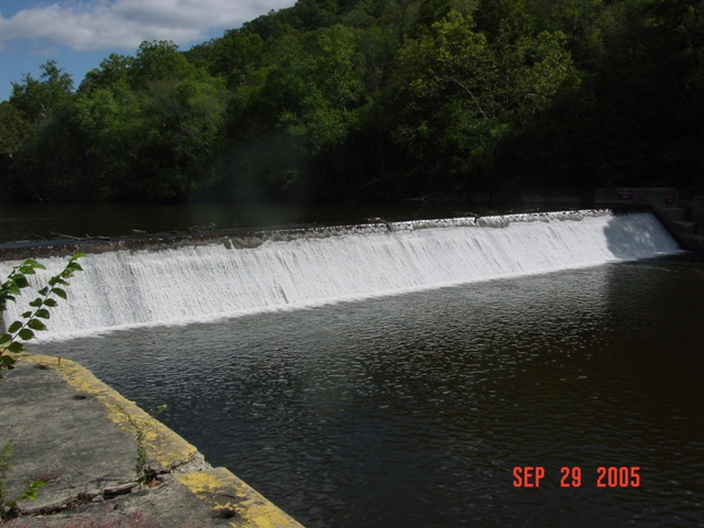
 finance.ky.gov
"Lock and Dam 14 were built from 1911-1917 and supports a pool of water that backs up into the forks. The original lock and dam were concrete structures. The structures are located two hundred and forty nine miles above the mouth of the Ohio River."
"1999 Sheet piling backfilled with gravel was placed across the main dam and capped with concrete, abutments were rebuilt with new release valves, derrick stone was placed below the dam, concrete cutoff wall was built in the lock chamber, lock filling valves were sealed"

Berea

The hydropower plant that Berea put in L&D #12 was considered a success, so they are installing one in L&D #14. It should be producing electricity by May 2024. However, this one is a completely different design with a different vendor (Voith), and it will generate 30% more power. The design uses a horizontal axis instead of a vertical axis. Not only does that reduce the amount of concrete that is needed ("reduces by 60%" compared to Lock #12), it allows the use of a submersible trash rack. It also has a movable spillway that can be lowered to allow the river to flush debris downstream. "The powerhouse will contain six Voith StreamDiver submersible turbine-generator units, consisting of four 14.9 StreamDiver axial flow 1490-millimeter propeller turbines directly coupled to a 645-kilowatt permanent magnet generator and two 8.95 StreamDiver axial flow 895-millimeter propeller turbines directly coupled to a 225-kilowatt permanent magnet generator. The total output of the plant will be 3,030 kilowatts." [Berea] I think the permanent magnets means this powerhouse can help restart the grid if there is a regional blackout.

Voith
It uses water to lubricate the bearings and cool the generator. Water lubrication eliminates the issue of oil polluting the river. (The bearings have a service interval of over 10 years. [issuu])
The are 7 standard sizes ranging from a head of 2-12m (6.5-40') and an output of 50-2,000kw.
(Someplace I saw the claim that the turbine was fish friendly. But I can't find that reference.)

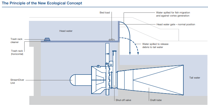
Voith
Note that the concrete work is just flat surfaces.

This diagram taught me how the horizontal trash rack works. Trash was definitely a problem with the #12 hydro plant.
Voith-pdf, p3
In addition to run-of-river applications, it can be used in canals for irrigation and cooling and in closed pipes.

The StreamDriver was included in this study of turbine choices. I did not read the article, but I want to note this reference for future study. The two graphs are from that study. (Banki is crossflow, which is new to me. And the difference between Kaplan and Propeller is another topic I need to research.)
Via ResearchGate
1
[It is interesting that Kaplan can achieve the same high efficiency as Francis, but is more efficient at lower flows.]

2


Monday, January 30, 2023

1910-1998 Kentucky River Lock & Dam #12 and 2.64mw Hydro near Ravenna, KY

(Satellite, 52 photos)

This was part of the Kentucky River Waterway.

The dates of operation come from AbandonedOnline.

While studying the truss bridge at Irvine, KY, I noticed on a satellite map that there was construction activity at this lock. They were building the Matilda Hamilton Fee Hydroelectric Station.

 finance.ky.gov
"Lock and Dam 12 were built from 1907-1910 and support a nineteen mile long pool of water. The original lock and dam were concrete structures. The structures are located two hundred and twenty one miles above the mouth of the Ohio River. A water release valve was installed in 1998 to transfer water downstream in times of drought."
"1997-1998 Sheet piling backfilled with gravel was placed across the main dam and capped with concrete, abutments were rebuilt with new release valves, derrick stone was placed below the dam, concrete cutoff wall was built in the lock chamber, lock filling valves were sealed."

Berea
"In Estill County, along a stretch of the Kentucky River, five turbine generators are converting a million gallons of water per minute into clean electricity. The 13-foot tall, 23,000-pound turbine generators represent just some of the marvelous technology being used at the Matilda Hamilton Fee Hydroelectric Station, the first hydro plant to be completed by an American college or university.  It is also the first small hydroelectric plant built in Kentucky in 94 years. Using the abandoned navigational lock would lower this cost by a third."
The project cost $11m, but they were able to get some federal and Kentucky tax credits to offset that cost.

Berea
"AHA enlisted the hydropower engineers at Kleinschmidt Group to design a powerhouse that could be “shoe-horned” into the lock. They would be able to do that with fully submersible turbine generators developed by Xylem, a leading water technology company based in Sweden. These turbines had significant advantages over conventional turbines. Because they were submersible, they were unaffected by flooding, and they were designed to last 50 years, twice as long as those used for wind or solar plants. Each turbine generator is capable of producing 528 kilowatts of power, for a total plant output of 2.64 megawatts. In addition, variable speed drives not only increased turbine efficiency, they allowed the plant to sync easily to a power grid with existing distribution lines, a significant cost saving."
The turbines are designed to last 50 years, which is twice the design life of wind and solar plants. It provides about half of Berea College's electrical needs. Every source I read claims it will keep 11,000 tons of CO2 out of the atmosphere. But no one mentioned a time frame. Is that over the 50 year designed lifetime for the project? (No. That is an annual savings. [HydroReview])

“The big thing we’re doing here is we’re using variable frequency drives,” Fairchild said, “which basically allows us to let the turbines run at whatever speed they want to run, rather than being fixed by the grid to run at a specific speed.” [Berea]
I'm guessing that the "variable frequency drives" rectify the output of the generators to DC and then invert it to 60hz AC. They said the technology was borrowed from the wind industry. But every wind turbine I've seen turns at the same slow speed.

We can see the holes into which the turbine units will be installed.
Jeremiah Potter, Jun 2020, cropped

It went online in May, 2021. The variable speed technology allows them to get 10% to 15% more power.
2:55 video @ 1:02
 
KentuckyToday, Berea College photo

Removing debris is obviously an operational cost of hydropower plants. The design for their second plant, which is at L&D #14, allows them to easily flush the debris downstream.
2:55 video @ 2:46

I hope the price of scrap steel was high when they removed the downstream gates.
Jeremiah Potter, Jun 2020


Sunday, January 29, 2023

1940,2022 KY-52+89 Bridge over Kentucky River & CSX/L&N at Irvine, KY

(Bridge Hunter; no Historic Bridges; B&TSatellite)

Street View, Aug 2022
[There is a newer bridge about a mile downstream that heavier vehicles can use.]

Before it was renovated in 2022.
Street View, Nov 2018

Any truss bridge that Kentucky decided to save is worth noting.
1 of 3 photos posted by Bridges & Tunnels
Irvine Bridge, which carries KY Routes 52 and 89 over the Kentucky River and CSX Railroad in Estill, Kentucky, underwent structural repairs, a deck overlay, and painting in 2021-22. The crossing was dedicated in July 1940. An all-day program was held in celebration of the new crossing, attracting nearly 6,000 people to the festivities that included live music, bicycle races, boat races along the Kentucky River, a boxing match, a wheelbarrow race, and a baseball game. It also featured an invocation from a pastor, numerous welcoming addresses, and concluding with a ribbon-cutting by Governor Keen Johnson.
➤ Check out more photos of the Irvine Bridge at http://bridgestunnels.com/location/irvine-bridge/

Saturday, January 28, 2023

1911 River Mill Dam and 25mw Hydropower on Clackamas River at Estacada, OR

(Satellite)

Clark Niewendorp posted
The River Mill Dam, a hydroelectric dam and powerhouse just north of Estacada, Oregon, on the Clackamas River was built in 1911. It is an example of an Ambursen-type dam, a concrete-slab-and-buttress dam design. Only three dams of this design were built west of the Mississippi, and the only one to survive.

I noticed that the dam has a fish ladder dug into the north bank of the river. I also noticed the pipe that was added to spray water into the river. Since the pipe's inlet is near the top of the lake, the purpose is not to add cold water to the river. Is the purpose to oxygenate the water or to create a flow in the river near the fish ladder and away from the hydro plant discharge? Or both? Or something else?
Satellite

This peak through the trees shows more of the fish ladder.
Sing PaPa, Aug 2022

HydroReview
25mw

Sing PaPa, Aug 2022, cropped

Sing PaPa, Aug 2022, cropped
 
They evidently still use the original five horizontal-shaft generators.
HydroReview

This dam does not look like a buttress dam to me. I expected to see a bunch of triangular walls that are perpendicular to the face of the dam. For example:
Roseland Dam via Structurae.net

I do see a bunch of parallel white lines in today's spillway. Did they fill in the spaces between the buttresses? 
No. In addition to the usual upstream slabs for a buttress dam, I think they added slabs on the downstream side to form a spillway. In other words, the dam has more void space than concrete on the inside. [HydroReview]
Satellite

Another photo that shows that it was important to wall off the buttresses to create a spillway.
OSU Special Collections & Archives : Commons, No restrictions, via Wikimedia Commons

Friday, January 27, 2023

1840s Enlarged Erie Canal Aqueduct and Road/Trail/NYC Bridges over Schoharie Creek at Fort Hunter, NY

Canal: (Bridge HunterHAERSatellite)
1910: (Bridge HunterSatellite, northern truss)
1929: (Bridge HunterSatellite, southern truss)


Aquduct

"Built 1839-1841, put into service 1845; six arches demolished 1915; three more have collapsed since." [BridgeHunter-canal] The eastern arches were demolished because they were in the main channel and caused ice jams. I found a date of 1969 for this photo. That date is significant because the three eastern arches have yet to collapse. Obviously, this photo was taken when the river was high because the flood plain is inundated. In the satellite images the flood plain is dry.
HAER NY,29-FORHU,2A--4
4. Looking northeast. - Erie Canal (Enlarged), Schoharie Creek Aqueduct, Spanning Schoharie Creek, Fort Hunter, Montgomery County, NY

This shows that the stone arches carried just the towpath. What carried the "trough" of water? Iron would be bleeding edge in 1840, but would wood be strong enough? Or was it wood beams and iron truss rods?
HAER NY,29-FORHU,2A--8
8. Towpath and trunk bed from southwest shore.

Note the "spur" canal below the canal that used the aqueduct. That is a remnant of the original 1820s canal. It was retained as a feeder canal for the 1940s enlarged canal. A guard lock was added where the remnant of the 1820s canal met the river to keep river flood water out of the canal. The walls of that lock are still preserved. [Photo of a plaque]
1945 Tribes Hill Quad @ 24,000

There is a lift lock a little east of the river where the feeder canal joins the main canal.
Satellite

When the 1820s canal was built, a dam was built downstream on the Schoharie Creek to form a slack pool which the canal boats used to cross the creek. All they had to build across the creek was a bridge for the towpath. After the 1840s canal was built, they still maintained a diversion dam on the creek to create a pool that fed the feeder canal. [Photo of a plaque]
HAER NY,29-FORHU,2A--30
30. Photocopy: Composite Map of Crossing Site by Daniel J. Mordell from Canal Society of New York State. Bottoming Out: Useful and Interesting Notes Collected for Members of the Canal Society of New York State. Vol. 18-19. Syracuse, 1962.

An arch places a strong lateral force on the pier. Normally, the arches on both sides of a pier balance each other. But since they removed some of the arches, the pier on the end lost its lateral bracing from the other side. So I presume that the arches have been falling like dominoes. This aqueduct has been a popular attraction in the state park. So, as part of a $1.7m rehabilitation, they are going to build a buttress for the end pier.
safe_image for $1.7M project will stabilize Schoharie Crossing aqueduct


While looking for the aqueduct, I noticed that there are two truss bridges just a little upstream of the aqueduct.

Road/Trail/NYC Bridge


The northern truss was a NYC bridge, and...
Nov 2021 Photo by Geoff Hubbs via BridgeHunter-1910, License: Released into public domain

Several photos by a snowmobiler

Trail/Road Bridge


...the southern truss was a road bridge.
Street View, Dec 2021

Both

NYC abandoned their bridge in 1981. So it was available to help handle the traffic on NY-5S when it became the detour for I-90 after I-90's bridge over Schohaire Creek collapsed in 1987. After the I-90 bridge was repaired, traffic returned to the road bridge and the railroad bridge became part of the Gateway Trail - Erie Canal Trail. But the southern truss, already weak, was damaged in 2011 by Hurricane Irene. So the road was moved to the stronger railroad bridge in 2015, and the trail was moved to the weaker road bridge. That is why we now see the trail crossing the road on both sides of the river.
Satellite

This was taken during the 1987 flood that wiped out the I-90 bridge.
uticaod, Source: New York State Thruway Authority


Thursday, January 26, 2023

1954 I-90 Bridge over Schoharie Creek Collapsed on April 5, 1987, Killing Ten People

(Bridge Hunter; no Historic Bridges; Satellite)

USGS (U. S. Geological Survey), Public domain, via Wikimedia Commons
Schoharie Creek Bridge collapsed

The replacement bridge.
Street View, Dec 2021

uticaod
"Schoharie Bridge Collapse Looking south over bridge approx. 4 hours after collapse. Source: New York State Thruway Authority"

uticaod. photo by Utica resident Toni DiMeo
[This shows the slope failure under the north side of the west abutment. And the erosion down by the river that caused that failure.]

uticaod. photo by Utica resident Toni DiMeo

The flood was the result of the double whammy of snow melt and an intense Spring rain. The normally 6' deep Schoharie Creek was 25' deep. The first span fell around 10:45am. Another span dropped about 1:15pm. [DailyGazette, paycount 2]

Four cars and one truck fell 84' into the creek. "The cause was determined to be a failure to properly design, build and maintain the bridge. Built in the 1950s, the bridge's supports had concrete footings dug 6 feet into the riverbed, instead of piles driven into the bedrock needed because the riverbed soil was vulnerable to washing away." [TimesUnion]

"A rebuilt bridge was fully opened to traffic on May 21, 1988. The legacy of the tragedy was a reexamining of the way the state inspected its bridges. A Federal Highway Administration report fourteen months after the collapse found over two-thirds of New York State's bridges to be deficient, the highest percentage in the nation. The state took over examination of all bridges, including those owned by the Thruway Authority and local governments. 'It drew attention to the way that the bridges were inspected, to the degree of inspection and to the need for underwater inspection for piers and abutments,' John Seligman, director of infrastructure services for Spectra Engineering, told the Post-Standard in 2007." [syracuse]

Since it took over a year to build a replacement bridge, a 1910 railroad bridge that was being used for a trail was converted to a road bridge in a couple of months to help handle the detour traffic on NY-5S. 

uticaod, Source: New York State Thruway Authority

I changed the order of these photos to try to put them in chronological order.
uticaod, Source: New York State Thruway Authority

uticaod, Source: New York State Thruway Authority

uticaod, Source: New York State Thruway Authority

uticaod, Source: New York State Thruway Authority

uticaod, Source: New York State Thruway Authority

uticaod, Source: New York State Thruway Authority

eng-resources, photo courtesy Howard F. Greenspan

I didn't bother reading the NTSB report because I found this report to be informative.
Some of my takeaways:
  • The scour hole under pier 3 was 9' (3m) deep and 25' to 30' (7.5m to 9m) long.
  • "The state also required diver inspections of the underwater structures every five years." But it had never been inspected in over three decades.
  • The design called for the sheet piles to be left in place and for the excavation to be backfilled with riprap. Instead, the piles were removed and the excavation was backfilled with erodible soil and topped off with some riprap.
  • A 1955 flood had probably removed the little riprap that had been placed by the pier.