Normally, an ingot train would run inside a mill between the teeming facility in the open hearth building, the mill's yard tracks to let the steel cool, and
the stripper in a rolling mill. [
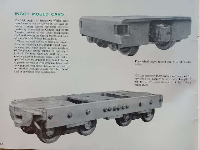
PracticalMachinist] Now ingots are obsolete because of continuous casting. The special heavy duty flatcars that carried the ingot molds were called ingot buggies.
 |
United States Steel Corporation posted
This ThrowbackThursday we're climbing aboard the USS Express! Check out this image of ingot molds in transit from our Gary Works in Gary, Indiana.
Seymour Long: Unique trucks on those cars there. What kind are they?
EJ Jaquay: Seymour Long Don't know for sure but I guess standard wheels with AP bearings on special bolsters. The heavy covers over them are likely there to protect the wheels from teeming splashes.
James Torgeson shared |
 |
Adam Piscitelli posted in Homestead, PA
This is an ingot buggy probably from OH4 where I worked as a greaser. The cars got so hot from the molten steel that the grease ran out or caught fire in the journal boxes on the axles. My job was to pack the axles with grease balls which were softball sized wads of scrap yarn soaked in grease. Spent a lot of time on my back stuffing wads into journal boxes. Added bonus: the cars were still smoking hot when we got them.
Al Monroe: did you use regular like mayo consistency grease or did you use thinner stuff like when grease separates.
Adam Piscitelli: Al Monroe Thin. Like maple syrup.
Al Monroe: Adam Piscitelli oh ok. That's what i figured. Great story. Love to listen/read old industry stories.
Ralph Tramontana: I worked at the soaking pits for a summer at National Tube in McKeesport. I was amazed that the train would pull the ingots all the way from Duquesne without them falling off the car.
David Lang Jr.: Where is this displayed
Dennis DeBruler: It is in the corner of a little park at 8th and West Streets, https://www.google.com/.../@40.40633,-79.../data=!3m1!1e3... |
 |
Frank Jacobs III posted
Ingot molds. Pittsburgh spelled without the “h”. Ken Hernandez: Getting inside them and cleaning them was the worst job I ever had. Dave Matergia: Ingot molds. Ingots are inside. Ronald Meiss: David Finch Shenango had foundries in Sharpsville,Pa , Buffalo New York and Neville Island. I worked in Sharpsville making molds!! David Finch: Ronald Meiss Years ago worked at an Engineering firm in Ambridge called Bollinger Corp and they designed new molds for Shenango |
 |
Graham Whitfield commented on Dave's comment
Spot on Dave. |
 |
John Bizub commented on Frank's post
Worked Remote control operator and Switchman U.S.Steel Ohio Works, Youngstown, Ohio. |
.jpg) |
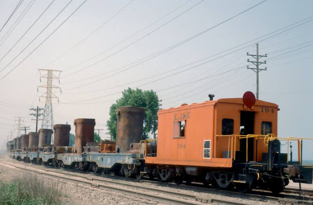
Larry Candilas posted
Heading for South Works coming from Gary, passing Hammond Water Plant.
Julio Ponce: Ingot molds?
William O'Neal Stringer: Julio Ponce yes
Dale Groh: Looks like some BEU's! (bottom-end-up).
Clarence Rutherford: What year?
Perry VanRosendale: Clarence Rutherford late 1980’s. Making armor plate for the Gary 210” plate mill. My peeps made the heats for the molds.
Larry Candilas: Dumb question maybe - why did they have to bring steel from South Works to Gary when Gary had so many furnaces?
Scott Pugh: Larry Candilas South Works had an electric furnace that made different alloy of steel that blast furnaces could not. Used for armor plate. Gary did not have an electric furnace. |
 |
Graham Whitfield posted
Cast of Rimming ingots leaving the Teeming Bay on route to the Stripper Bay. Great bunch of guys on the Locos, the Drivers and Shunters serviced the Teeming landings, Mould Bay, Stripper Bay and Soaking Pits. British Steel Llanwern 1978. [The are some interesting comments about life in a steel mill.] |
 |
Rocky Black posted
Mold yard was a crazy place to work.
Rocky Black: We spent a couple days trying to keep the switches open before. The storm was bad and high winds really cold. They got upset because I had a guy get antifreeze barrels in a bucket loader and we made trenches around the switches and dumped antifreeze into them. Foreman was happy everything was working but thought for sure we would get in trouble for it. The guys were just getting so worn out I had to do something. The mills didn't say anything 😂 they love it when everything is going good.
Tom Scheidemantel: Worked in stripper/mold yard at Cleveland J&L . In the 80’s. If you could handle that you were promoted to teeming isle then BOF melter/ turn foreman . 42 years I did it all .
Thomas Leslie: Ran Mold Yard Crane Johnstown Pa. Beth Steel 1980 thru 1990's. So glad I wore a respirator most of the time back then.
Rocky Black: I worked in the mold yard at inland steel. We had a winter storm going and my crew worked a double trying to keep the switches open. [In a later comment he says he is not sure of the location.]
Art Wright: Phillip Claxon Could be Gary, layout and stripper buildings, exactly the same.
David Conkle: I used to scarf the top of the molds. With 4ft scarring torch. That job sucked!
Rocky Black: David Conkle I was putting the boards in the top for awhile. We had one guy fall into the mold. He was ok.
Rocky Black: Paul Grattan yep they have to be hot to head for the pouring stand. He fell in and was able to stand up not touching the sides, the lucky part was I noticed he wasn't standing there putting boards in kind of quick. If he had been wearing a safety belt it would have made him lay up against the side until we noticed him gone. [I believe that means a "safety" belt would have killed him.]
Peter M. DeStefano: I bought a lot of scrap broken molds over the years.
The integrated mills usually wouldn't melt them so we sold them to the big Electrics like Northwestern. And Valley and Vulcan couldn't put them in their cupolas. |
 |
Graham Whitfield commented on Rocky's post
Great photo, worked in the Stripper Bay, Soaking Pits and Slabbing Mill at British Steel Llanwern Works. The Loco crews and Crane drivers were fantastic. We had some spectacular derailments. I wish I had taken photos of our Stripper cranes in action. Talk about a ‘Red Hot mad house.’ Continuous casting wiped out the Mould Bay, Teeming Bay, Soaking Pits etc. It’s a long time ago but it was a wonderful place to work.
|
Michael Riha
posted two photos with the comment: "
Been awhile since I posted, so William O'Neal Stringer
's post about the ingot train inspires these shots from one of my first trips to Calumet Ave on the lakefront...long before CN or even the casino."
I recall handling one of these had 2 300’s. Was interesting to hold the speed at 15 mph when loaded when the 300’s did not have speedometers.
I worked at US Steel South Works where we filled those molds with molten steel from the #4 Electric Furnace shop. They were sent to Gary Works to be stripped and rolled at the plate mill as our plate mill was closed in the early 80's.
Yes, but the steel had different qualities. They made plenty of regular steel at Gary Works.[What we are looking at is really the molds holding the ingots. A machine called the
stripper will lift a mold by the round lugs near the top and then a hydraulic plunger will shove the ingot out.]
 |
| 1 |
 |
| 2 |
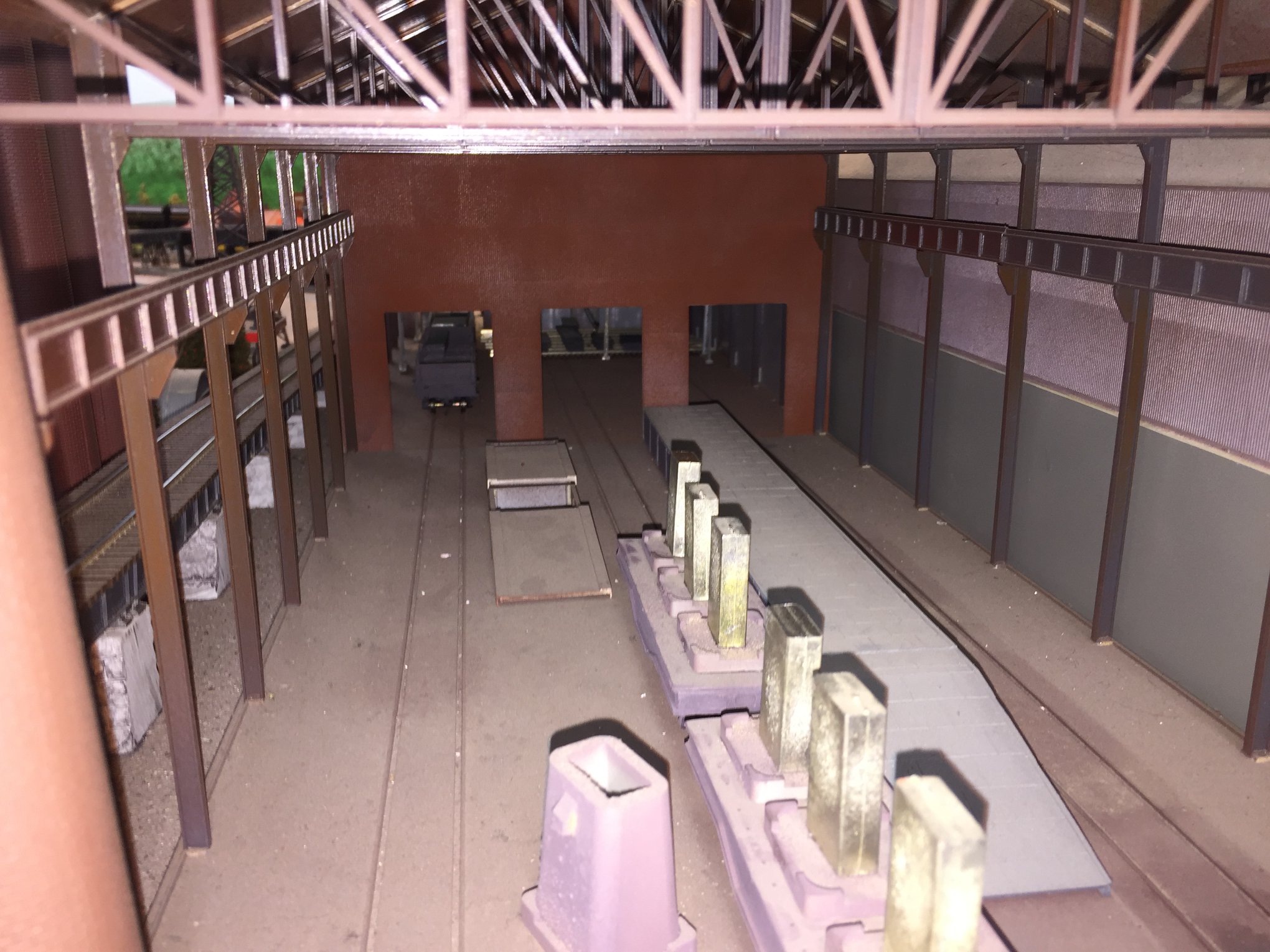
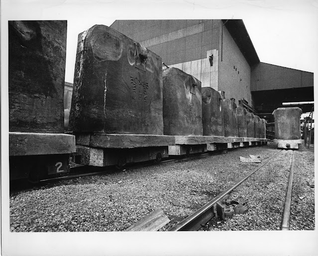
Here we can see why they were called buggies. It looks like just two molds per car 2-axle car.
 |
TrainWorldCity
[Another model. Since ingot trains normally stayed in a mill, there won't be too many railfan photos of them.] |
 |
TrixTrains
[The ratio of one mold per two axles is rather common.] |
The buggies were also used to carry trays holding scrap metal that were used to charge open hearth furnaces.
 |
| U.S. Steel Gary Works, April 19, 1912 |
 |
One of the photos posted by Michael Mora about the lighthouses at the mouth of the Calumet River
[Note the cut of ingot cars in the middle of the photo. We are looking at the south side of U.S. Steel South Works.] |
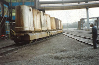
Ingot stripper in Homestead, PA I could not find a date for this photo. The steel mill is not only gone,
the brown land has been redeveloped.
John W. Coke
shared his
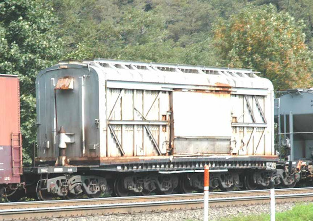
post of two photos with the comment: "Lehigh Heavy Forge Corporation, Hot ingot transport car. Photo by Barbara Ryan, Horseshoe Curve, October 2004."
Richard Middlekauff It is used to transport hot steel billets. We used to see them regularly thru Harrisburg from Steelton, hauling billets to Lehigh Heavy Forge. We had a Conrail engineer explain that there was a 16 hour window from when the billet hit the floor of the car to delivery at the forge. They would pull four or five of the cars up from Steelton to the Harrisburg yard. They hustled to connect them to the front of an eastbound stack train and take off.
Patrick Carroll I would assume that it was around 1600*-1800* Fahrenheit
Jason Kliewerhttp://www.rrpicturearchives.net/rsPicture.aspx?id=308787
Noe Gutierrez LHFX 37000 is a former Bethlehem (BFIX) car. It's a "hot ingot car" https://lionelllc.wordpress.com/tag/flat-cars/ Four 3-axle Buckeye trucks enables the car to have a rated capacity of 744,500 pounds, or just over 372 tons.
 |
| 1 |
 |
| 2 |
 |
Mikl Lussier commented on John's share
From their site :
<<Lehigh Heavy Forge has earned the elite status of Forgemaster.
Starting with ingots up to 285 tons, our 10,000 ton open die hydraulic press produces the largest forgings in the western hemisphere with ship weights exceeding 166 tons. In addition we also operate a 3,000 ton open die hydraulic press for work roll forgings, billets and smaller forgings of various configurations with ship weights starting at 10 tons.>>
[So the continuous caster has not made all ingots obsolete. Only those ingots that would be rolled. Since rolling mills are used to make beams, plates, rolled sheets, bars and wire, rails, etc., I imagine most steel is no longer initially cast as ingots.] |
 |
| William O'Neal Stringer commented on his posting about a train order mixup between Kirk and South Works |
 |
William O'Neal Stringer commented on his posting about a train order mixup between Kirk and South Works
One per car. Rocked side to side, think the soeed limit was 10 mph. Also a time limit on loaded ones to the stripper on Gary mill.The "J"had two divisions in Gary. Kirk Yard, and Gary Mill Yard. Mill yard switchmen were only allowed to perform service in that mill. KIRK yard was a where trains were assembled for going to the many connections that the J had. At one time it connected with every carrier that went into the Chicago swiching district .also out of KYD yard transfers handled cars into and out of Gary mill, plus local connections with many other carriers and other industries, and also transfer service to and from USS South Chicago. I hired in 1968,At that time we had about 50 regular assignments, plus extras put on as needed. Five men on a crew, foreman two helpers ,engineer and fireman, when I retired in 2003 ,a hogger and two ground was normal. |
 |
Bill Parkinson posted
Some ingot action at the No.1 open hearth back in the 1970's AIS works Port Kembla.
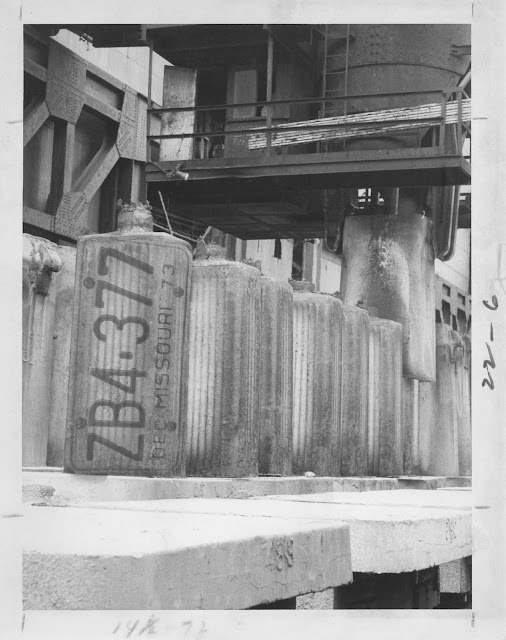
How do you define an ingot? For us in a remelt plant in Pgh, it was about the size of a household water heater, a little longer Anybody? In the Open Hearth days at U S Steel in Youngstown, Ohio our most common ingot size was 19" x 22". For us a heat would be about 42 ingots. We made a lot of bar stock that was rolled at the McDonald Mill, now McDonald Steel. We also poured ingots for blooms that would go to the 40" Hot Strip in McDonald. We had 2 Blooming Mills, one was a 40", the other was a 43". The biggest ingots that we poured were 26" × 43". So, billet size is measured on the end of the bar. Under 36 square inches is a billet over 36" it is a bloom. Our 43" mill would take a reheated ingot, roll it down to a bloom, then advance it without reheating to finish rolls where it was slit and rolled down to 4×4", 2×6", 2×8", and 2×2" size. So, I have seen casters that cast bars, but you can make bars from larger ingots. The smallest ingot moulds were probably for pipe rounds. Just a note of clarification, the 19"×22" size was the actual ingot size at the top of the mould. The moulds were about 7 feet tall. I remember stringing those ingot molds onto rail cars for the next heats! Then they’d go to stripper mill then to the soaking pits to be reheated for the old slab mill then on to the hot strip furnaces and turned into coils, and to the cold mill if finished.... Ford Rouge Plant Dearborn, MI  (from ‘74 to ‘16) a lot of changes and closures now. |
Robert Ries
posted three photos.
 |
1
|
 |
2
|
 |
3
|
Robert Ries
posted two photos.
Seen one splash over on auto’s look like a bomb.
 |
1
|
 |
2
|


.jpg)