These are notes that I am writing to help me learn our industrial history. They are my best understanding, but that does not mean they are a correct understanding.
I rode Amtrak's California Zephyr through Colorado on Thanksgiving, 2019. One of the things I saw was obviously the penstocks for a hydroelectric power plant.
From a satellite image, it is obvious that the two light brown penstocks on the left side of the photo above feed the turbines. I don't know what the dark brown penstock on the right is for. The two horizontal "brown lines" is I-70 plus US-6 plus US-24. The lower highway is the eastbound lanes and the upper highway is the westbound lanes. (A couple of "white spots" is glare off the observation lounge window.)
Photo from COLO,23-GLENS.V,1--4 from co0088
4. SHOSHONE HYDROELECTRIC PLANT, SOUTH ELEVATION; TWIN PENSTOCKS AND FOREBAY ABOVE THE PLANT; HOIST HOUSE AND NORTH CABLEWAY TOWER ABOVE THE SPILLWAY TO THE RIGHT; TAIL RACE BELOW U.S. HIGHWAY 6 BRIDGE. - Shoshone Hydroelectric Plant Complex, 60111 U.S. Highway 6, Garfield County, CO
Street View from the upper (westbound) I-70+US-6+US-24 lanes
Street View from the lower (eastbound) I-70+US-6 lanes
17. Photocopy of photograph (original print at the Public Service Company of Colorado, Shoshone Hydro Plant Collection, Glenwood Springs, Colorado) Photographer unknown, Circa 1935, cropped
18. Photocopy of photograph (original print at the Public Service Company of Colorado, Shoshone Hydro Plant Collection, Glenwood Springs, Colorado) Photographer unknown, Circa 1935, cropped
19. Photocopy of photograph (original print at the Public Service Company of Colorado, Shoshone Hydro Plant Collection, Glenwood Springs, Colorado) Photographer unknown, Circa 1940, cropped
It is a run-of-river plant that generates 15mw using two units. [Xcel] The intake diversion dam was built just east of Shoshone Falls.
As I have seen in other places, the "falls" appears to be a rapids.
11. SHOSHONE INTAKE DAM, VIEW TO THE NORTHWEST. RESTROOM BUILDING AND STEAM CLEANER BUILDING ARE SEEN BELOW THE WEST SPAN OF THE BRIDGE; HOIST HOUSE AND CABLEWAY TOWER APE ABOVE CENTER. - Shoshone Hydroelectric Plant Complex, 60111 U.S. Highway 6, Garfield County, CO, cropped
12. SHOSHONE INTAKE DAM, VIEW TO THE NORTHWEST. WALKWAY ABOVE DAM ON THE LEFT; GATE HOUSE TO DIVERSION TUNNEL BELOW EAST BRIDGE SPAN; HOIST HOUSE ABOVE CENTER; TRANSFORMER AND SWITCH RACK ON THE RIGHT EDGE OF PHOTO, cropped
The above shot of the dam was cropped and exposure corrected. I thought it would be interesting to show what the raw version of the previous photo I took of the dam looked like. I took this one as soon as there was a break in the treeline, as did the person beside me.
Note that the gates are closed. It is no surprise that November would be a dry season for the Colorado River. I had noticed that the flow was almost gone in the river. When I noticed that, I said out loud "Where did the river go?" which was rather embarrassing. I took a photo of the very low flow in the river. The train was going rather slow through Glenwood Canyon, but a tree did manage to sneak into the foreground of this photo.
I took the photo below because of the bridge. But I now understand that we are seeing the upstream part of the 245' dam on the left. And the river is going under the bridge into 16'8" wide by 13' high diversion tunnel that was dug 12,450' through the mountain to the penstocks. The dam was originally built with bear trap gates, but they proved to be a maintenance problem so in 1930 they were replaced with four tainter gates. The dam also has flash boards that are believed to be part of the original construction. [historic-structures]
To carry its generated electricity across the state, Colorado Central Power erected a 153-mile transmission line from the Shoshone plant to Denver by way of Leadville, Georgetown and Idaho Springs. A second line ran to Glenwood Springs. About 37 miles of the Denver line were completed east of Leadville in 1907, and the entire line to Denver was finished by late 1908 or early 1909. After rising more than 1500 feet from the canyon floor, the line crossed some of Colorado's most rugged terrain, including Hagerman Pass (12,055 feet), Fremont Pass (11,346 feet) and Argentine Pass (13,532 feet). When it was completed, the Shoshone line was the highest transmission line in the world. Today the alignment remains essentially the same as the original, but the transmission towers have been replaced, and the entire network has been significantly altered. [historic-structures] It has become obvious that their source was HAER-data.
The original transmission line was 90,000 volts. That line has been upgraded to 115,000 volts, but most of the power generated is now consumed on the western slope. This HAER record was made in 1980 because the proposed I-70 construction would have "an adverse visual effect." [HAER-data]
As seen in the above satellite image of the rapids and this image of the dam, the river is not always dry between the dam and plant. That is, sometimes the flow in the river exceeds what is needed to fill the diversion tunnel. I checked Bing Maps for river flow. The image of the dam is unusable because it is in the shadow of the canyon wall. But an image of the rapids shows the flow was very low. In fact, it is hard to see where the river is. I include the image at full resolution because Bing Maps would not give me a link.
(The "creating link" comment never was replaced with a link.)
This video shows a heavy flow downstream of the dam.
(new window)
The Moffat Tunnel is one of several diversion tunnels that have been built to carry water from the Colorado River Basin to the towns on the east side of the Rockies. But this power plant has water rights to what it originally could handle, 1250cfs. And because of the age of those rights, it has priority. During droughts, the managers of the intakes to the continental divide tunnels have to reduce their flow so that the power plant gets its flow. Because the plant returns all of its water to the river, these water rights provide water for uses downstream such as drinking and irrigation of peach trees. [HCN] This flow is also helps sustain "an important part of the local economy: rafting, kayaking and fishing." Maintaining a high flow in the river also helps dilute the salt coming out of salt springs, which of course benefits the farmers who use the water for irrigation. In fact, some farmers would like to buy the plant just to get the water rights. 15mw is a drop in the bucket compared to most power plants, but 1250cfs is not just a drop. "But Xcel continues to invest millions in maintenance at the plant and the utility says they have no plans to sell Shoshone or its water rights." [KRCC] The flow also helps save four endangered fish species. [InkStain]
Notice the Beaver Valley Bowl building on the left:
Before the modern dams so Ohio still low here...
Rochester,Penna
1930
Paul Ruby: Well, it was a speakeasy in 1930 and wasn't a bowling alley until 1945.
[Some comment explain that the bridge on the right is the cantilever bridge being built. And the railroad bridge is out-of-frame to the right.]
A photo that includes 1932 cantilever bridge.
Little Beaver Historical Society posted 1948 aerial view confluence of the Beaver and Ohio river. [The Ohio River road bridge is on the left, and the Ohio River railroad bridge is on the right.] Lloyd Scott Hardin shared
Dennis DeBruler: This is the first photo I have seen that has the 1932-86 cantilever bridge.
Later, I saw this closeup of the cantilever bridge.
Happy 2026! Let's break the ice with this photo showing the frozen Ohio River & the old Monaca- Rochester Bridge ( 1932-1985) & the boats across the river forced up on land!...
Photo source:Arnold McMahon. Beaver County Album #2
Exact year: unknown
Little Beaver Historical Society posted Construction of the first Rochester /Monaca Bridge. The first of 3 bridges between the two towns this original bridge crossed very near where the Beaver Valley Bowl building is. The next bridge was where the current bridge sits.
Dale Barrett: built in the late 1890's, stood till the new bridge was built in 1932.
According to some comments on the above post, this 10th Street remnant went to the bridge.
Shell Pennsylvania Chemicals posted
In this week of Thanksgiving, we'd like to express our thanks to everyone who attended the Monaca Community Meeting on Thursday. We enjoyed the opportunity to meet you in person, and appreciate your valuable thoughts and feedback. (photo credit: monacapa.net)
[Shell is building a huge polyethylene plant in Monaca.]
Climbing Skies posted The Rochester-Monaca Bridge, spanning the Ohio River, on a cloudy day in Beaver County, PA.
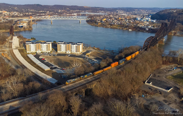
Ian Bowling posted CSX Q331 passes over the ex P&LE Beaver Bridge to continue it’s journey West towards New Castle, PA. The tracks below are the NS the Cleveland Line and in the distance to the left, are the tracks for the NS Fort Wayne Line. Enjoy! Bridgewater, PA Roger Riblett shared [The first road bridge is this bridge.]
Climbing Skies posted A distant confluence of the Beaver & Ohio Rivers, along with some of the bridges, from near Allaire Park in Monaca Heights in Beaver County, PA.
Gretchen Brubaker Harich commented on a post Saw it as it [LST-325] went up the river to Pgh!!!
Climbing Skies posted Barges being brought back down the Ohio River and in between the E. Rochester / Monaca & Rochester / Monaca Bridges in Beaver County, PA.
Climbing Skies posted Coming back down the Ohio River, under the Rochester-Monaca Bridge, with empty barges in Beaver County, PA.
Malachi Issac: Nice pic. He's got quite the mixed tow of empties, couple jumbo barges, 4 stumbos, couple standards and some sand flats possibly, the captain also knows to keep the flat side of the tow on his port side to slide down the long lock wall at Montgomery locks and dam a few miles down river. He also has the head square on his starboard side so as to avoid collision with the middle wall bullnose at the locks also. He's definitely a seasoned pilot. All in all, great pic my friend.
Dennis DeBruler: Malachi Issac Thanks for the explanation. I was surprised to see four barges abreast. Your comment reminded me that 35' x 200' barges are considered jumbos and the standard size is 26' x 175'. So four standard sized barges are a foot skinnier than three jumbo barges and easily fit in a 110' wide lock. I watch tows on the Lower Ohio, Illinois and Mississippi Rivers, and I have seen only 15 jumbo tows. I did not know that the standard size is still used.
Malachi Issac: Dennis DeBruler Yes, all jumbos aren't 200' though ......most rake end jumbos are 195'x35 and all box end jumbos are 200'x35'.
Yes sir you are correct on the 4 standard barges.175x26...there are still some standards in service, sometimes rare, but still out there and hauling cargo....You'll see a lot more of them on the upper Mon river, with what little industry is left up there.
I was aware that the Tacoma Narrows Bridge was designed with a thin deck made of steel girders instead of a deep truss so that it would look "streamlined." I was not aware that this was a fad that other engineers adopted until recently. In fact, steamlining was a general fad in the 1930s. Four months after the Tacoma Narrows opened, engineers learned that fad was wrong because the bridge was torn apart by torsional waves. This bridge was David Steinman's streamlining mistake because he designed it with a lightweight deck. He learned it was unstable during construction so he added cable and floor stays to (almost) stabilize the bridge. (The Bronx-Whitestone Bridge was another "streamlined" bridge that had problems with wind. The designer, Othmar Ammann, added stiffening trusses to the deck to stabilize it.)
The popularity of Eggemoggin Reach as a yachting area called for a 200' wide channel at midspan with a minimum 85' underclearance, placing the roadway at 98.7* above mean water level. At the same time, the depth required for foundations at this location called for minimizing the length of the approach spans. This height problem was solved by employing steep 6-1/2 percent approach grades and a fairly short 400' vertical curve at the center of the main span. In this manner, the needed height was attained and the approach viaducts were kept to a minimum length. [HAER-data]
To meet the requirement of opening before the Summer tourist season, they had to work during the Winter. To minimize the hardships of working in the Winter weather, they pushed prefabrication techniques past what had been used before. In addition to assembling prefabricated modules for the deck and tower, they also built the cofferdams from prefabricated sections. And they used the prestressed twisted-strand cables that they developed for earlier bridges such as the 1931 Waldo-Hancock Bridge. [HAER-data]
Before the bridge was finished, unexpected wind-induced motion in the
relatively lightweight deck indicated the need for greater stability.
Diagonal stays running from the main cables to the stiffening girders on
both towers were added to stabilize the bridge. [HAER-data]
Two years after the Tacoma disaster, Stienman's reinforcements got their test on Dec 2, 1942. "That day a severe storm ripped down the Maine coast, smashing into the bridge with winds of up to 80 miles per hour. The bridge oscillated in 12-foot waves that snapped a quarter of the cable stays, cracked the expansion joints, caused the suspension cables to slip through the cable ties, and generally wrought havoc on every part of the bridge. The damage was extensive, but when the gale blew itself out, the bridge was still standing.
"The storm left Steinman more convinced than ever that he was on the right track. What the bridge needed, he decided, was more of the same. Steinman added another, far more extensive set of cable stays, and he didn’t stop there. By 1944 there were vertical stays between the tops of the towers and the roadway, transverse stays that crossed over the roadway, and zigzag stays from the roadway to the main cable and back, crisscrossing the secondary cables the whole length of the span. The bridge became an enormous cat’s cradle of metal rope, as if it were woven by the hands of a giant." [InventionAndTech, p5]
"More recently, in 1993 the bridge received additional protection from wind. A special system of fairings that direct wind over and below the girders were attached to the outside of the girders." [Historic Bridges] These fairings were evidently the result of wind-tunnel testing done by the Federal Highway Administration. [ScienceDirect; ResearchGate, but I didn't request full-text]
This photo shows some gaps in the faring on the side of the deck. That makes it easy to understand what was added in 1993. If you look very closely, you can see diagonal cables as well as the usual vertical suspender cables. I think those diagonal cables are the cable stays that were added to help save the design. I'm still trying to figure out what the "floor stays" were.
When David Steinman heard that the Tacoma bridge was experiencing wind driven problems, he wrote to the authority and offered to provide a solution to their problem. But his offer to help was turned down. Four months later, when the bridge tore itself apart, he let people know that he offered to solve the problem, but he was refused. But given the need for additional solutions to stabilize this bridge and the more extreme length-to-dept ratio of the Tacoma bridge, some engineers think that no amount of additional cables could have saved the Tacoma. [InventionAndTech]
Mike Reynolds posted two photos with the comment: "Deer Isle Bridge in Maine."
1
2
Comments on Mike's post
The caption on this construction photo implies that some of the prefabricated pieces were quite large.
PenobscotBayPress, Penobscot Bay Press file photo
The Mainland side tower being raised on finished piers and base in summer of 1938.
Unlike the Waldo-Hancock Bridge, MDOT successfully completed rehabilitation of this bridge in 2008. The narrow deck, 20' curb to curb, was replaced 9' at a time in sections of 200' so that traffic could use both lanes for most of the crossing. [cianbro]
The pier work consisted of removing deteriorated concrete and using stay in-place forms made of steel for pouring the new concrete. Leaving the steel forms in place will help protect the piers from ice. [ChildsEng]
Additional work was planned between July-Dec, 2013. [CastinePatriot] But that work spilled over into February, 2014. [WeeklyPacket]
HAER ME,5-BUCK.V,1--1 1. GENERAL VIEW UPSTREAM WITH BUCKSPORT IN BACKGROUND, LOOKING NORTHEAST - Waldo-Hancock Bridge, Spanning Penobscot River at U.S. Route 1, Bucksport, Hancock County, ME Significance: The Waldo-Hancock Bridge was the first long-span suspension bridge erected in Maine, as well as the first permanent bridge across the Penobscot below Bangor.
Technologically, the Waldo-Hancock Bridge represents a number of firsts. It was one of the first two bridges in the U.S. (along with the St. Johns Bridge in Portland, Oregon, completed in June, 1931) to employ Robinson and Steinman's prestressed twisted wire strand cables, which were first used on the 1929 Grand Mere Bridge over the St. Maurice River in Quebec. The prefabrication and prestressing of the cables decreased the number of field adjustments required, saving considerable time, effort, and money. As an additional experiment in efficiency, the Waldo-Hancock cables were marked prior to construction, ensuring proper setting. This method had never been used before and proved successful in this instance. These innovations, invented and pioneered by Steinman, were a significant step forward for all builders of suspension bridges.
The Waldo-Hancock was also the first bridge to make use of the Vierendeel truss in its two towers, giving it an effect that Steinman called "artistic, emphasizing horizontal and vertical lines." This attractive and effective truss design was later used in a number of important bridges, including the Triborough and Golden Gate bridges.
The Waldo-Hancock Bridge was noted at the time for its economy of design and construction. It cost far less than had been appropriated by the State Highway Commission, which enabled the construction of a second bridge between Verona Island and Bucksport. As part of U.S. Route 1, it remains in active use today, nearly 70 years after its completion.
Specification: 2040' long with a clear span of 800' between towers. One span of 800', two of 350' each, 20' roadway with 2 3-1/2' sidewalks, stiffening trusses 9' deep, each cable 9-5/8" in diameter consisting of 37 strands of 37 wires. Deck is 135' above water level to allow passage of large ships. Total cost: less than $850,000.
I include this view of the tower since this bridge pioneered the use of a Vierendeel truss in the tower. From a distance, a Vierendeel truss appears to be made with rectangles instead of triangles.
But if you look closely at the cross-members, they have plenty of triangles. I'm lucky that the portal street view in Bridge Hunter still has an image. Note only do the cross-members have lots of triangles, but there are vertical members that run through all three cross-members. The inside vertical members were eliminated in more modern bridge towers.
"Built 1931; bypassed by new bridge 2006-07; Demolished 2012-2013; Removed from NRHP 12-18-2013" [Bridge Hunter] This is evidently another example where 80% Federal funding for a new bridge makes it cheaper for a state to build a replacement than maintain a nice looking bridge. I can understand how they let the cables rot so bad that it would no longer safely hold traffic. But since it was handling traffic, how can it be so bad that it can't be used by pedestrians? It seems like it would take a couple more decades of rotting before it would be too weak to hold itself up. (Pedestrian traffic has to be negligible compared to the weight of the cable and truss.)
John Weber posted Traveling in Maine I was fortunate to take this photo of these two bridges. Now the old bridge is gone. Taken at the Penobscot River crossing. Called the Historic Waldo-Hancock Bridge.


%20Bridges%20_%20Deer%20Isle%20Bridge%20in%20Maine%20_%20Facebook%20and%203%20more%20pages%20-%20Personal%20.png)


