A video of the removal of the lift span of the temporary bridge while the lift span of the new bridge goes up and down. Note the height of the blue aerial platform on this side of the old bridge tower. That looks very top-heavy to me.
 |
| Screenshot (source) |
 |
| Bing |
 |
A swing bridge was built in 1902.
 |
| Photo from MassDOTdesc [The swing span is in the background of this photo of a shipyard] |
 |
| The Warshipologist posted [The foreground is the shipyard.] |
The original deck truss bridge was built in 1936 and rehabilitated in 1954. "Route 3A has been the main route to the South Shore, ever since the Hingham and Quincy Bridge and Turnpike Corporation was formed in 1808. A swing bridge was built here in 1901-1902, but proved a bottleneck, both to shipping, with the shipyard upstream, and to extensive South Shore traffic. The new bridge, with a total length of 2,216 feet, and a 60 foot roadway, included a 175-foot draw span, of the double leaf rolling lift type, designed to open or close in one and a half minutes." [HAER]
 |
| Photo from HAER |
 |
| Boston Public Library, CC BY |
"In the late 1990's the 1936 bridge was found to be badly deteriorated and in 2002, traffic was directed off it and onto the current temporary bridge. In 2004, after appropriate historical documentation under Section 106 of the National Historic Preservation Act of 1966, the 1936 span was demolished. Though the temporary bridge is safe today and regularly inspected by MassDOT, it is rapidly reaching the end of its useful life and must be replaced. The new permanent vertical lift bridge will cost approximately $244 million to build and will carry the 32,000 vehicles that use the 3A corridor for at least 75 years to come." It will improve the vertical clearance from 175 to 250 feet. And in the closed position it has a clearance of 60 feet allowing most sailboats to pass underneath without impacting traffic flow.
[MassDOTdesc]
 |
| weirdpix, License: Creative Commons Attribution-NonCommercial-NoDerivs (CC BY-NC-ND) USNSM USS Salem CA139 & Vertical Lift Drawbridge |
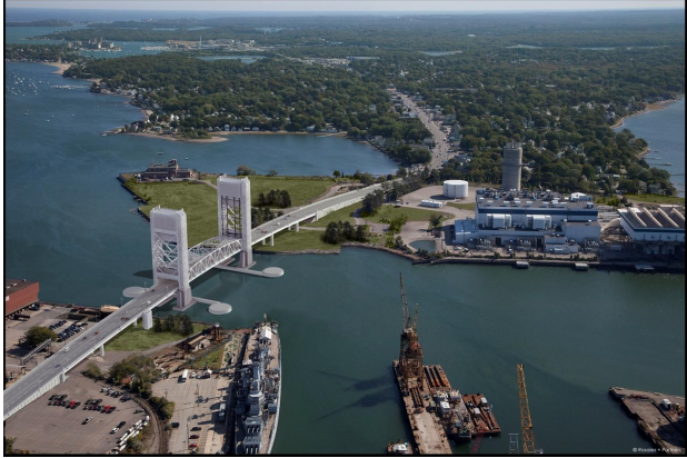 |
| Figure 2: Rendering of the proposed vertical lift bridge in the closed position. |
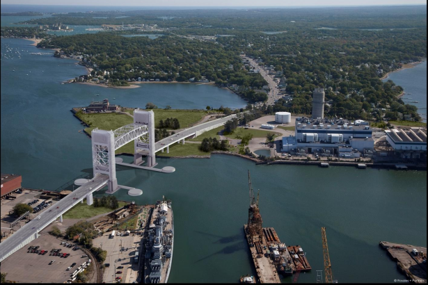 |
| Figure 3: Rendering of the proposed vertical lift bridge in the open position. |
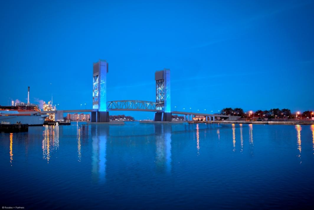 |
| Figure 4: Rendering of the proposed vertical lift bridge at night. |
I wonder which country the sheaves were made in. The contractor should have sent someone there to test the metal during fabrication. Some of the eight sheaves were shipped with cracks! Each sheave is 20 feet in diameter, weighs 85 tons, and costs $1.4 million. I'll bet they sent someone to supervise the construction of the replacements. "State transportation officials declined to say who manufactured the sheaves, where they came from, what happened during the fabrication process, or how many broke....Mayor Susan Kay of Weymouth said she was told that the sheaves were made in Alabama and that the delay would be about 10 months." As I suspected, I helped pay for that bridge: "About 80 percent of the Fore River Bridge funding will come from federal grant anticipation notes, which are bonds backed by the future federal grant money. The other 20 percent will come from Massachusetts taxpayers." [BostonGlobe] As mentioned above, the 1.75 year delay turned out to be about another year past 10 months.
 |
| May 18, 2017, Presentation from MassDOTdocuments |
The disadvantages of the two types of movable spans are discussed starting on page 18 of the Vollmer Study. One I had thought of: "a larger substructure." I guess no one on the study committee bothered to look at how the Chicago engineers alleviated this disadvantage --- the pony truss. In fact, page 86 of the report indicates that they looked at only one bascule bridge for reference. The three joint disadvantage was new to me. I guess they couldn't invent some sort of gutter to alleviate this disadvantage. The disadvantage of wind load when the bridge is open is serious because they wanted a solid deck. By the way, in Chicago the first non-swing bridge was for Halstead Street, and it was a lift bridge. But a lift bridge was not tolerated for streets closer to the loop for aesthetics reasons. Aesthetic considerations is why Chicago was forced to learn how to design bascule bridges.
On page 23 of the Vollmer Report they provide a cost estimate for each of the options considered. They don't indicate if the bascule bridge had 40 or 70 feet of clearance. But the movable options differ by just a few tens of millions of dollars. I'll but the cost overrun because of the delay caused by the bad sheaves cost much more than that. At least I did not have to help pay for the tunnel option, which was much more expensive. Considering how badly Massacusettes screwed up the Big Dig through Boston, I'm very relieved they did not choose the tunnel option.
Furthermore, they never considered the option that came to my mind about half way through the report. Since the need for such a high and wide movable span is because of oil tankers going to the Citgo Terminal, build a pipeline north from Citgo to share the dock at Sprague Terminal. Then you can have a fixed bridge at just 70 feet, which would have been much cheaper than any of the considered options and had the advantages of low maintenance and no traffic disruption.
Jay Cashman, Inc. posted two photos with the comment:
Jay Cashman, Inc. completed the demolition of the superstructure of the Fore River Bridge in just 8 weeks. We were limited to one 7-day and one 8-day closure by the U.S. Coast Guard to entirely remove the 210’ lift span structure topping out at over 200’ off the water. With lifts over 500,000 lbs., Jay Cashman, Inc. mounted a Manitowoc MLC650 on a barge. This is the first of Manitowoc’s MLC650s with the new shifting counterweight technology. We are continuing work on removing the substructure concrete and piles. Check out the photos below!
 |
| 1 |
 |
| 2 |
Ben StalveyGroup Admin Awesome few MLC 650s on siteBen StalveyGroup Admin Very neat similar setup as the Duluth Aerial Lift bridge
 |
| 1 |
 |
| 2 |
The project is done and they are now selling the construction equipment.
 |
| Joe Sweed posted 302,000lbs Randy King That tug sold today [5/22/2019] |
A video of cutting the pipe piers with demolition shears attached to an excavator. The comments discuss why the load was held in the air while the barge was moved. A comment provides another video of the work the day before. I normally hate profile videos. But for cranes it almost makes sense. But here is a time lapse video (source) demonstrating that Danny really needs to learn how to take a horizontal format video. It shows the counterweights moving in and out as the weight on the boom changes.
(new window)
(new window)
This video made by the company operating the "blue stuff" has such bad (way too "jerky") editing that it makes me glad we have the above video from the bridge contractor.
(new window)
This video of the span move was much easier to watch.
(new window)
No comments:
Post a Comment