Saturday, June 26, 2021

Bus US-90 1957 Tunnel and Bridge Crossing of Harvey Canal in Harvey, LA

Bridge: (3D Satellite) (Evidently Bridge Hunter considers this to be UCEB because I could not find it. The bride is indeed concrete, but it strikes me as worthy of documentation.)
Tunnel: (Bridge Hunter; Satellite)

I spent more time than I care to admit looking at the Louisiana DOT web site to find information about these bridges. Lots of documentation of the nature "we will make plans." But very little information about what those plans were unless you count lists of closures and asphalt projects as plans.

Bus US-90 used to cross under the Harvey Canal south of the locks with a tunnel. Now it crosses over the canal with a pair of bridges. But the tunnel is still used for local traffic and pedestrians [OnlyInYourState]. I already studied a tunnel replacement with a high fixed bridge in Belle Chasse.

AAroads has a history of Bus US-90, but I could not find any info on these bridges. In particular, what is the clearance? They look a lot higher than barge traffic would require. When were they built?


Seth Jarrett posted two photos.
1
[The comments note that there are two towboats at Bolinger Quick Repair.]

2


Friday, June 25, 2021

1948 135mw Center Hill Dam on Caney Fork near Lancaster, TN

(Satellite)

The dam was built in 1948. [Video]


Photo via details via $1.8b saved via Facebook
Center Hill Dam on the Caney Fork River in Lancaster, Tenn., discharges water from its spillways April 8, 2021. (USACE Photo by Lee Roberts)
This is one of four dams that held 1.8m acre-feet of water from a 7.01" rain event during March 27-28.
This rainfall storage kept the river level in Nashville at 40.55' instead of a predicted level of 55.7' if the dams did not exist. The flood stage in Nashville is 40'.

We can clearly see the peak in the blue line that happened in late March.
USACE-basin

USACE-basin

USACE-dam
Three 45kw generators can supply an average city of 125,000 people.
The max height is 250'. The length is 2160' of which 1382' is concrete and 778' is earth.

CJ McDowell posted
Center Hill Dam in TN.
 
Arlind Dukagjini posted
Center Hill Dam built in 1948

Nicole Sweeney posted, cropped
Center Hill Dam, about 1949
Lloyd Scott Hardin shared

WKRN
This is a second dam that I have learned about that was built on a cave system and cost the USACE a lot of money. The first one was the 1913 Hales Bar Dam that got replaced by the Nickajac Dam in 1967.
In 2005 this dam was classified as a high-risk dam and the USACE spent 15 years and $353m to fix the foundation.

"The good news is, that it’s all fixed now. But it was a monumental engineering feat that took three steps to complete and fifteen years to complete.
"First, there was a grouting project at the main dam embankment and left rim. The contractor pumped flow-able concrete into the foundation to fill voids.
"Then there was a 2.5-feet thick foundation cut-off wall installed on the lake-side of the dam. It extends as deep as 308-feet from the top of the dam, deep into the solid-rock foundation to prevent future seepage through the limestone.
"There were also repairs made to a secondary auxiliary dam on the east side of the main dam. Some refer to it as a ‘fuse plug’ dam that would be used to alleviate pressure on the main dam if a major flood ever occurred."

For those fifteen years, the reservoir was drawn down to 18'. That left all of the recreation facilities around the lake high and dry.

I presume this is the fuse plug. It looks like this was another valley that needed a dam.
Satellite

Nashville district posted seven photos with the comment: "LANCASTER, Tenn. (Nov. 5, 2021) – The National Inventory of Dams is being updated at the end of the year and the U.S. Army Corps of Engineers plans to feature Center Hill Dam in a video as part of its rollout with the public."
Cory Fisher: Did you get a picture of the low oxygenated releases too?
1

2

3

4

5

6

7

Screenshot
Are we seeing water that is leaking through the foundation of the dam? If so, I can't believe the reservoir is still full. Hydropower doesn't seem to be worth that level of risk.

I could not find any details (diagrams) about the work that was done. Note that the information I did find came from the press and not USACE's web site. But it was a while since the street view car drove over the dam, so it captured some of the repair work.
Street View, Aug 2013

Street View, Aug 2013

Street View, Jul 2014

And they were doing something beside the dam as well.
Street View, Aug 2013

USACE, Nashville District posted six photos with the comment:
Modernizing Hydropower at Center Hill Dam
The major turbine-generator replacement project at Center Hill Dam, completed in 2021, marked a significant investment in the region’s renewable energy future and was the first major turbine generator rehabilition in the Cumberland River System.  This comprehensive rehabilitation modernized critical powerhouse equipment, replacing 75 year old turbine runners, generators, and associated systems with upgraded, high-efficiency technology. Investing in infrastructure upgrades ensures that legacy hydropower facilities continue delivering dependable, carbon-free power for the communities that rely on them. This is a strong example of how modern engineering can preserve and enhance critical energy infrastructure.
1

2

3

4

5

6


Thursday, June 24, 2021

Frederick Douglass Tunnel to Supplement the 1873 B&P Tunnel in Baltimore, MD

(South Portal Satellite; North Portal Satellite)

B&P = Baltimore and Potomac

Record of Decision

The original plan was to bore four tubes. But the current plan is to bore just two tubes for the passenger trains and leave the freight trains in the old tunnel. This will eliminate diesel train fumes from the ventilation facility of the new tunnels and save more than $1b. The two tubes are supposed to cost "only" $4b. It also cut two years off the construction time so that it will take "only" 10 years. The design is supposed to accommodate adding two tubes for freight trains. (If they can bore two tubes for $1b in two years then what are they doing with the extra $3b and 8 years? It sounds like an additional expense is that the MARC commuter trains will be electrified.)
Amtrak via Railway Age via Progressive Railroading

Some of the $3b includes rebuilding a 4 mile route and building a new MARC station. Also, some track is being moved to flatten some curves so I some properties need to be bought.
Amtrak and www.bptunnel.com
"The B&P Tunnel, located in Baltimore, dates from the Civil War era. At nearly 150 years old, it is the oldest tunnel Amtrak inherited and a single point of failure for MARC’s busiest line (the Penn Line) and the Northeast Corridor."  [RailwayAge's caption]
The speed limit will increase from 30 mph to 100 mph. The new tunnels will have emergency egress pathways and ventilation systems.
In addition to the old tunnel falling apart, "there are no fire and life safety systems to keep passengers safe in the event of emergencies." [ProgressiveRailroading]

Amtrak-facts
"The age of the structure, combined with excessive amounts of water leaking into the tunnel walls and flowing underneath the track floor, has led to falling bricks and concrete, small portions of the wall collapsing and settlement (sinking) in the track floor."


Is code 1.1, GUIDEWAY AND TRACK ELEMENTS, the digging of the tubes? Note this estimate was made back when they were planning on doing 4 tubes. It seems to me that category 8 is a fudge factor of a billion dollars.
Record of Decision, pp 32,33

I skimmed the four Appendixes of the Record of Decision, but I could not find any information on "new bridges" that one article listed as part of the project.

June 2022: Marty Bernard posted
https://www.rtands.com/track-construction/amtrak-launches-procurement-phase-for-bp-tunnel-replacement-program/?utm_source=&utm_medium=email&utm_campaign=33061
Amtrak launches procurement phase for B&P Tunnel Replacement Program
Erich Houchens: It's about time they did something about the B&P tunnel. I began my railroad career working in the towers of Amtrak's Baltimore division. One of the towers I worked at was B&P Jct which controlled signals and switches at either end of the tunnel. Back in the 70's the track in the tunnel was so bad that it was referred to as "Block'em & Plug'em" tunnel. Amtrak did put a concrete floor in the tunnel in the early 80's which stopped the derailments. Current plans are to take it out of service once the new tunnel opens and rebuild it with a single track.
William Russ: Baltimore's 2nd tunnel might be a better description as the B&P tunnel will be retained for use by MARC trains.

Mar 10, 2023:
safe_image for Amtrak Kicking Off $6B B&P Tunnel Replacement Program
"Two separate tubes with up to four tracks total in the new tunnel would enable speeds up to 110 mph."
Only passenger trains will use the new Frederick Douglass Tunnel. Freight trains will continue to use the old B&P tunnel.

Feb 27, 2024:
safe_image for Initial Demo Begins for Amtrak’s Frederick Douglass Tunnel Program
Marty Bernard shared

Wednesday, June 23, 2021

Drovers Cabbose

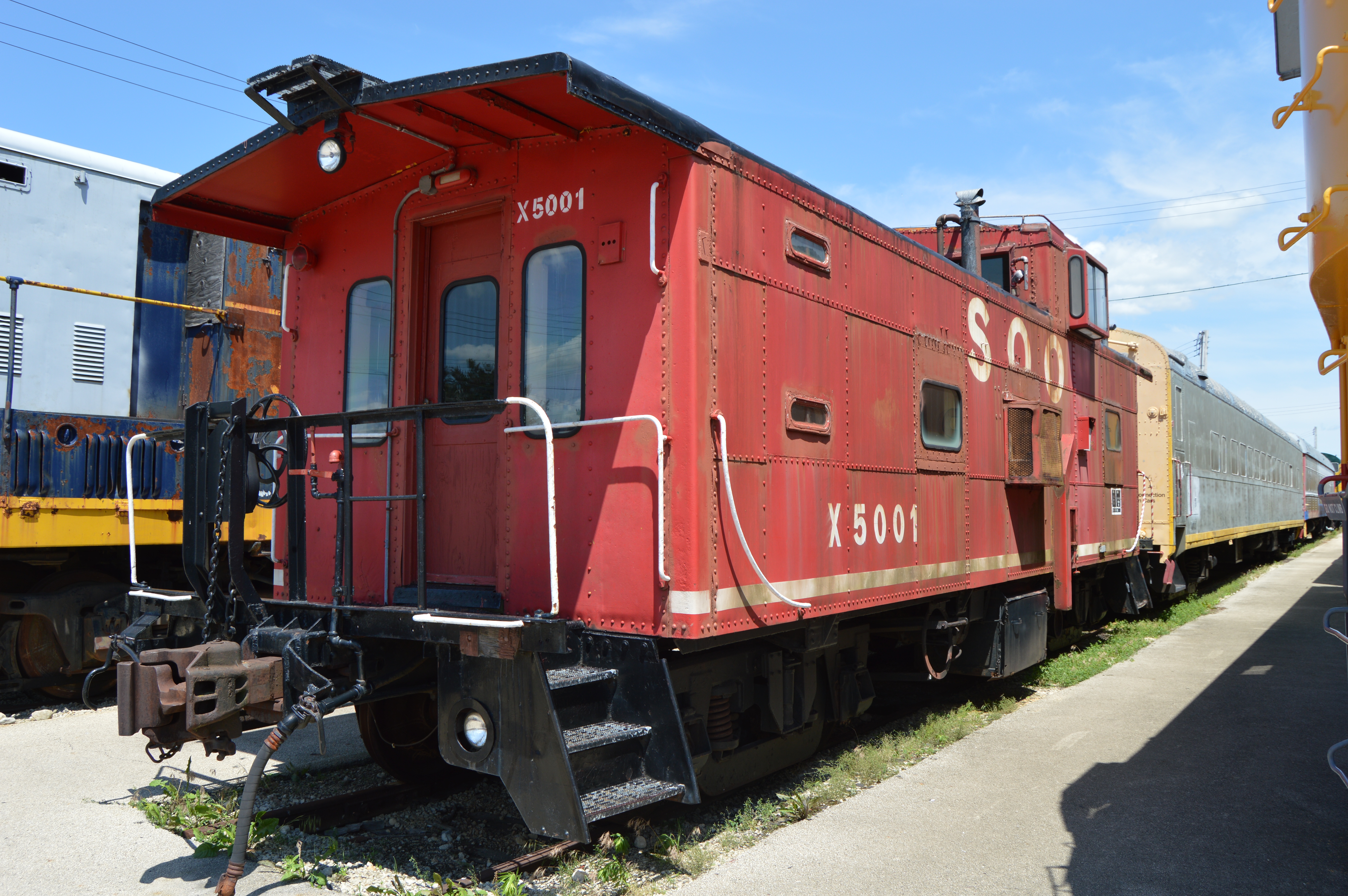
This SOO caboose at the Illinois Railway Museum has a sign explaining that it was converted from a drovers caboose to, as a Facebook comment by Sam Carlson called it, a poor man's business car. [I'm sorry that I lost the link for the Facebook post.]

20150627 2092rc


Sam also mentioned that this caboose was not built as a drovers car. Another comment explained what a drover car was:
Larry Ellis Reed Correct me if I'm wrong, but a "drover's car" would have been a hybrid of caboose and day coach as ran on stock trains heading to the major livestock markets (which, in the former Milwaukee's case, would have included the stockyards in Chicago, Milwaukee, South St. Paul, Sioux City, Sioux Falls, Omaha and Kansas City) as accommodated such wanting to sell their cattle, hogs or sheep thus.

A banana messenger's car, which ran on banana trains, was similar.

In any case, drovers thus riding up to market would get return tickets on conventional passenger trains (subject to restrictions on certain high-end prestige trains not accepting Drover's or Banana Messenger tickets).
The drovers were responsible for herding the animals at the intermediate rest stops and at the final stock yards. I assume the banana messengers were responsible for making sure the refers were at the correct temperature.
 
Some comments confirm that this X-181 was a drovers caboose.
Maykel Sanz posted
Jim Hebner: X-181 was a "one-of-a-kind" caboose. It was originally built in April 1953 by GN's Waite Park shops as X-100. It was renumbered to X-181 in 1966. It spent most of it's life near and around St. Cloud, MN and later GN's Hutchinson branch, pulled by an equally unique NW-5 locomotive. Now in Devil's Lake, ND alongside a bar.

Maykel Sanz posted
Michael Ballard: I bet that Great Northern caboose was the world's longest caboose, even longer than the drovers' cabooses that the Western Railroad companies used, on their cattle trains.

Great Memories and History of Fort Wayne, Indiana posted
A little known, five-mile long branch of the Wabash ran between Helmer and Stroh, Indiana. The branch was built in 1899 to serve a cement plant and was out of service by 1945. The town of Stroh must have been bustling with the cement business as a 1901 Stroh newspaper reported the freight agent took in $4800 in freight charges. Stroh also had a limber yard and a combined flouring mill and grain elevator. Of note is the caboose in the photo; it appears to be set up for passengers and LCL freight.
Loralee Taylor Dennis DeBruler, your mom helped drive sheep from this depot to the farm.
Tom Robison That's called a Drover's caboose. For trains transporting livestock, the drover's caboose was where the stockmen rode. The caboose would have seats/bunks for them. The stockmen took care of the animals during the trip at rest stops. Later on small railroads used them to transport a small number of passengers from stop to stop, which was less expensive than buying a dedicated passenger car.


Tuesday, June 22, 2021

Louisville and Portland canal by the Ohio River at Louisville, KY

At the Falls on the Ohio, the river bed falls 26 feet in three miles. I didn't realize until I saw the following photo that there was actually a falls here. I thought it was a rapids. It turns out, it is both. In addition to a falls, it had three rapids called chutes. From north to south there was the Indian, Middle and Kentucky Chutes. The Indian name got changed to Indiana by the 1890s.

Canal Society of Indiana posted
The Ohio River forms the lower border of Indiana and flows from Pittsburgh PA to the Mississippi river near Cairo, IL. It was free flowing except for a 2 mile stretch near Louisville, KY where it makes a 22 foot drop over a limestone ledge. There were 3 chutes through the rapids at the “Falls of the Ohio”. The “Indiana Chute” was the widest and closest to the Indiana shore. Here flatboats had to decide to hire a pitot to shoot the falls or transport their cargo 2 miles around the falls on the Kentucky side of the river.

Canal Society of Indiana posted
The falls at Louisville only allowed a one-way trip downriver as no boats could be taken up river. This was fine at the time for flatboats carrying settlers moving west and goods for New Orleans. The first steamboat, the New Orleans, arrived on the Ohio River in 1811. A new era demanded a bypass canal. On which side of the Ohio River would this canal be built?

Canal Society of Indiana posted
Indiana organized canal companies 3 times to build a 2.75 mile canal from Jeffersonville to just below the falls. The first attempt was in 1805 when Indiana was just a territory. After Statehood in 1816 another company called the Ohio Canal Company was chartered and this effort was also supported by Cincinnati merchants. Funding faltered and no construction was performed. The third attempt was the organization of the Jefferson Ohio Canal Company. Ground was broken on May 4, 1818 and some dirt moved. A lottery was held in 1819 to raise funds but, like the canal, was a failure.
In 1825 Kentucky formed The Louisville & Portland Canal Company. With federal support the bypass canal was completed in 1831 at a cost of about $1 million. With several later improvements, this canal still operates today.
See indcanal.org - March 2019 The Tumble & Historical Archives - Tour Guides

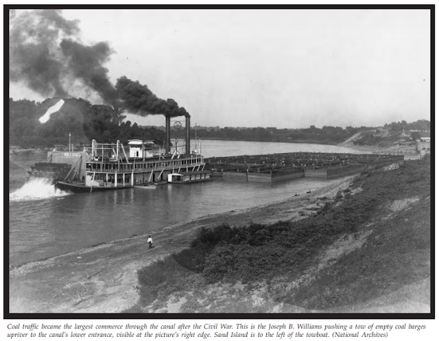
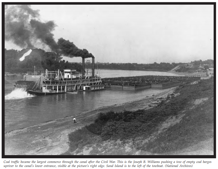
The 1831 canal had four flights of locks at its downstream end. But it had competition from the chutes. As with the St. Lawrence River, the canal was used going upbound, but boats would continue to use the rapids when going downbound if the water was high enough.
louisville.edu, p48

Cincinnati’s marine designers began to adjust to the canal’s dimensions, building steamboats that were 185 feet long by 43 feet beam, filling the lock chambers to near capacity. To offset the dimensional limits, steamboats loaded with freight to a depth of nine feet used all the water in the canal by crabbing, or pulling through the canal backwards, their paddlewheels dragging them across the mud flats on the bottom. It might take them an entire day to get through the canal in that fashion, but it allowed continuing on to New Orleans or St. Louis without transshipment. [louisville.edu, p82]
The Library of Congress has plans for the 1856 and 1871 enlargements. But they are not digitized.

Peter Zimmerman posted
The Ohio River circa 1906. Canal locks at Louisville, Kentucky. 8x10 inch dry plate glass negative, Detroit Publishing Company.
(unknown photographer)
James E Reising: The TRANSIT was a local harbor tug, she caught a lot of the Howard launchings, brought a lot of logs to the shipyard from the log raft storage area behind 6 Mile Island. She also worked for the Combine shuttling loads between the Pumpkin Patch fleet, just below 6 Mile Island, to the White City fleet, where Chickasaw Park is today, during low water periods. Looks like that's what she doing in this photo.
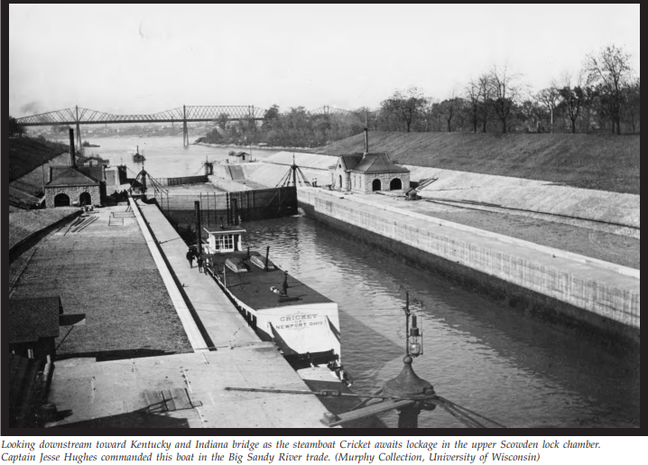
[Note the original 1886 Kentucky & Indiana Bridge in the background.]
Good Old Days posted
Canal locks at Louisville, Kentucky on the Ohio River. c.1906.
Lloyd Scott Hardin shared
James Stark: Down bound towards the “singing” highway/railroad bridge with swingspan…

1886 Bridge, Public Domain, from Bridge Hunter Old via Dennis DeBruler
Dennis DeBruler commented on James' comment
Since what I saw over the navigation channel was a suspended cantilever span rather than a swingspan, I checked out the bridge. Does this mean that the bigger steamboats had to use the rapids to go upstream as well as downstream? The photo is Public Domain.
James Stark: Dennis DeBruler Only if the river stage was high enough would they shoot the falls; Steamboats lowered their stacks when necessary…
Dennis DeBruler: Thanks. I forgot that the smokestacks were hinged.

booklet, p4
ca 1900
 
Richard Sattich posted
Tarascon steamboat in the Louisville & Portland Canal. 1904. ... The "Tarascon," built in 1863 for the Louisville and Henderson Mail Line, was used in service during the Civil War. Here the boat sits at the Louisville & Portland Canal waiting for the locks to open. It traveled as far as the Alabama River and Mobile, before returning to the Ohio River. Caption under the photo reads, "Leaving Locks.
Jeff Noble: Tarascon is one of the oldest family names in Louisville, or more specifically in Shippingport, which at one time was its own town, incorporated in 1785, on the land which is now cut off from Louisville by the Portland Canal. The Tarascons and others arrived there in 1806, predating the canal, and renamed the town of Campbelltown as Shippingport. They had previously purchased the site in 1803. They were shipbuilders and later operated a flour mill. Shippingport was a residential area until well after the 1937 flood. Eventually the entire area was bought by the Corps of Engineers in the late 1950s and the final residents either left or became deceased by 1964.
Lloyd Scott Hardin posted
Frank X Prudent: The TARASCON are in the photo is a later boat. The 1863 TARASCON was a sidewheeler.
Doug Crawford: Frank X Prudent yeah I was gonna say that’s an incredibly long lifespan for a wooden Ohio river steam boat.

Dennis DeBruler posted
Logical page 138 and PDF page 150 in
TRIUMPH AT THE FALLS:
THE LOUISVILLE AND PORTLAND CANAL
Comments on DeBruler's post

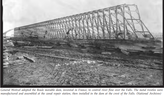
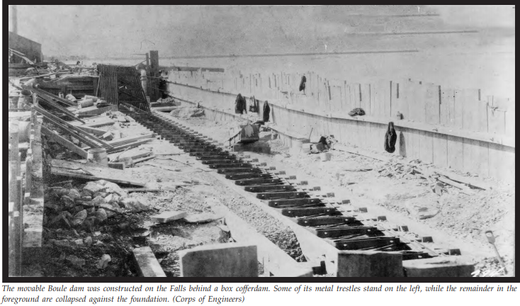
In the 1870s, a crest dam was built to maintain a depth of 6' in the Louisville docks and at the head of the canal during low water. In the 1900s it built a new dam to maintain a 9' depth to accommodate tows carrying coal. This dam used the recently developed Portland cement instead of stone masonry for the foundation. Concrete was also used in the fixed weirs. Some of the dam was Boule trestles. The segment at the head of the Indian Chute used Chanoine wickets "that could be raised or lowered faster than the Boule sections." [USACE, p210] Frequently, during the dry season, work was done to widen (by blowing away rock) and channelize (by building dikes) the Indian Chute until it achieved a width of 400'. [USACE, p214]

USACE, p194

Reducing the flow in the spillway of the Boule Dam in 1930. They hinge a frame up and then insert a panel ("metal shutter"). [booklet, p7] Boule was the type of wicket dam design. Part of the crest dam above  the Middle Chute was replaced in 1879 as an experiment. It was considered a success. [USACE, p171] The Boule dam shown here was in the 1920s dam at the head of the Indian Chute.
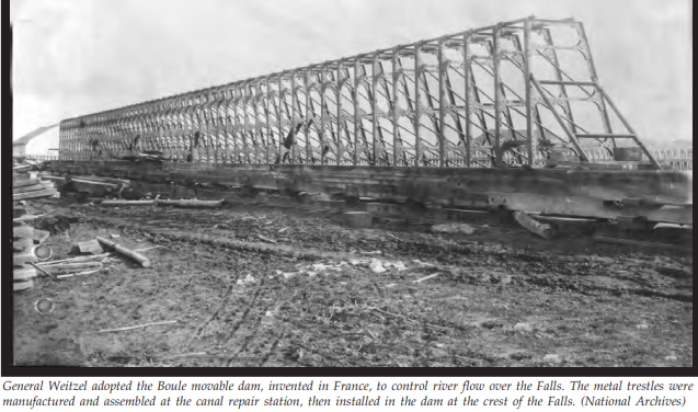
USACE, p171
[(This page is also the beginning of the INDIAN CHUTE EXPERIMENTS. The original name was lost by 1890, and it became known as the Indiana Chute. [USACE, p193])]

USACE, p180

USACE, p146
 
Richard Sattich posted
Canal locks, Louisville, Ky. 1906. ... Locks on the Ohio River at Louisville, looking down the canal from the river bank. There are no boats visible in the locks; the gates are closed. Many structures are visible along the bank on the opposite side of the canal. Published by Detroit Publishing Co.; bears manufacturer's number 10431.
Stephen Saalman: Much of the stone to build the locks came from the Cannelton, Indiana rock quarries.
Lloyd Scott Hardin shared
Michael Gore: Great look back. The view is actually looking up (not down) the canal.

USACE, p146
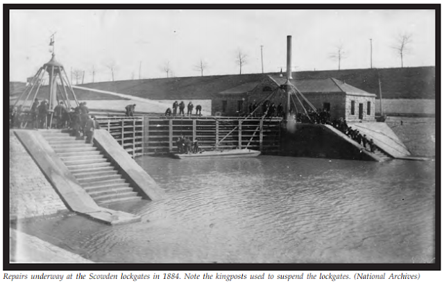
They were repairing damage caused by the 1883 flood.

USACE, p189
[K&I Bridge]

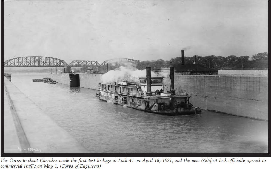
In 1910, Congress passed a bill that approved a 53 lock & movable dam plan to canalize the river with a minimum depth of 9'. In that plan, the new dam built here would be #41. The plan called for an 85'x600' lock even though all of the other locks would be 600'x110'. The width of the lock was changed to 110' and the width of the canal was changed from 170' to 200' so that standard tows could pass each other without one of them having to duck into a passing basin. [USACE, p214] William McAlpine was in charge of the design and construction of the 600'x110' lock,
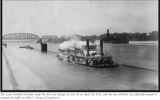
USACE, p221
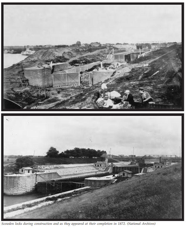
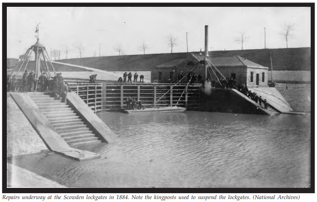
"Built of concrete and steel, integral to comprehensive plans for developing the entire Ohio River, Lock 41 set the pattern for twentieth century waterways engineering. The 1830 locks and fifty-foot-wide canal had served as the principal navigation structure bypassing the Falls for forty-two years until the completion of Scowden locks in 1872. In the second phase, Scowden locks and the eighty-six-foot wide canal served for forty-nine years until 1921. Although the epitome of engineering when built, Lock 41 and the 200-foot-wide canal were to serve as the principle structures in the third phase during the forty years from 1921 to 1961, when riverborne commerce expanded to volumes far exceeding the maximum predicted by the Lockwood Board in 1908 when it justified the canalization project."

Because WWI caused the price of coal to go up and because the ice storm of 1918 heavily damaged the existing crest dam, William McAlpine advocated building a new dam that was 8' higher than the damaged dam. This extra pool height would eliminate the need for dam #40 and would provide more head for hydroelectric power. [USACE, p227] A public-private partnership was formed similar to the one that was pioneered by the 1913 Hales Bar Dam. The L-shaped dam that we see today was adopted to deliver the full 37' head to the powerplant built between Rock Island and Shippingport.

The lock walls did have to be raised and the lock gates had to be replaced with longer gates. [USACE, p231]

USACE, p229

louisville.edu, p154

David Gulden posted
PEAVYS FREDERICK B WELLS by the portland canal now the AMY FRANCIS for MMT


As part of the 1960s initiated effort to replace most of the wicket dams on the Ohio River with gated concrete dams, a 1200'x110' lock was added in 1961 and the canal was widened from 200' to 500'. The name of the complex was changed from Lock and Dam 41 to McAlpine Locks and Dam. The wicket controlled short part of the L dam was replaced with Tainter gates. That meant that tows could no longer use the Indian Chute. All river navigation had to pass through the canal and locks.

For information about the second 1200'x110' lock that was finished in 2009, see McAlpine Locks. For more information about the dam and the fossil coral reef it protects, see McAlpine Dam. I still need to write some notes about the powerhouse.