The Rion-Antirion Bridge- Greece
The Rio–Antirrio Bridge, officially the Charilaos Trikoupis Bridge, is one of the world's longest multi-span cable-stayed bridges and longest of the fully suspended type. It crosses the Gulf of Corinth near Patras.
It is considered to be a creation of extraordinary engineering. Built in an area with high seismicity, it spans a 3 km-wide straight across the Gulf of Corinth, northeast of the city of Patras on Peloponnesus, Greece and links the town of Rion on Peloponnesus with the town of Antirion on the Greek mainland, approximately 250 km northwest of Athens, Greece. Each end of the bridge sits on an opposite side of the expanding Corinthian Gulf rift zone.
General Information
The Rion-Antirion Bridge is considered to be a creation of extraordinary engineering. Built in an area with high seismicity, it spans a 3 km-wide straight across the Gulf of Corinth, northeast of the city of Patras on Peloponnesus, Greece, and links the town of Rion on Peloponnesus with the town of Antirion on the Greek mainland, approximately 250 km northwest of Athens, Greece. Each end of the bridge sits on an opposite side of the expanding Corinthian Gulf rift zone.
Measuring 2,880 meters (m) long (9,449 ft) from end to end and 28m wide (92.4 ft), the Rion-Antirion Bridge is considered to have the longest continuous, cable-stayed, fully suspended deck in the world, measuring 2,252 m in length (7,388.45 ft).
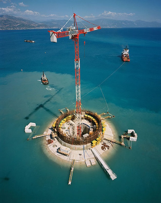
Each of the four vertical structures are constructed with pylons that rest upon 90 m (297 ft) diameter, reinforced concrete caissons that sit upon a gravel layer on the sea floor, 60-65 m (198-214.5 ft) below the surface. A typical vertical structure measures 220 m (726 ft) high from the sea-bottom to the pylon head.
By May of 2004, main construction was completed and the bridge was inaugurated on August 7, 2004, a week before the opening of the 2004 Olympics in Athens, Greece. The Olympic torchbearers were the first to cross its length. The bridge reduces travel time across the straight from 45 minutes (via ferry) to less than 5 minutes (by car).
The official name of the Rion-Antirion bridge is the “Harilaos Trikoupis Bridge”, in honor of Harilaos Trikoupis, a 19th century Greek prime minister who was the first to suggest the idea of building a bridge between Rion and Antirion, across the Corinthian Gulf.
The project’s total cost was 630,000,000 euros and financing for the bridge was secured by way of using 10% share capital, 45% state financial contribution and 45% from loans from the European Union’s financial institution, the European Investment Bank, guaranteed by a group of commercial banks (Gefyra, 2007).
On April 13, 2005, the Rion-Antirion Bridge was given “The Outstanding Civil Engineering Achievement (OCEA)” award by the American Society of Civil Engineers (ASCE). This was the first time, since 1960, that the award had gone to a project outside of the United States.
Other awards include: the prestigious “Outstanding and Innovative Lighting Designs Award” (2005) given by the International Association of Lighting Designers (IALD)(fig.2); “The Outstanding Structure Award of 2006” given by the International Association for Bridge and Structural Engineering and “The Outstanding Project Award 2007” given by the Deep Foundations Institute.
The Gulf of Corinth: Seismicity and Geophysical Characteristics
The Gulf of Corinth in Greece is one of the most seismic regions in Europe and contains one of the fastest opening, geological rift zones in the world. The rate of north-south expansion near the project site is estimated to be about 1.6 cm per year and the tilting and uplifting of its southern shore, locally in some areas, has been estimated to be at a rate of approximately 1 mm per year (Cordis Project, 2005; Bell, McNeill & Henstock, 2006).
The results of a three-year GPS survey, which was undertaken to determine how much and in which direction the land-mass on either side of the rift zone was moving, confirms that the land masses, in general, move constantly and independently of one another, and that random movement events of up to 5.2 cm have been observed (Hytiris & Kominos, 2001).
Profiles of the seabed along the proposed site of the bridge showed steep slopes on both sides and a long horizontal plateau, about 60-65m (198-214.5 ft) below sea level. Geological investigations at this same site suggested that the depth of the sediments, composed mainly of thick layers of clay, mixed in some areas with fine sand and stilt, reached to depths of more than 500m (1,650 ft). Additionally, explorations of the seabed in this area, to a depth of 100m (330 ft), encountered no bedrock (Gefyra, 2007; LCPC, 2007).
The Rion-Antirion Bridge: An Engineering Challenge
Engineers had to overcome many unique engineering challenges due to the wide assortment of potentially dangerous, natural conditions present in the vicinity. The robust seismicity of the area, the ongoing spreading of the Corinthian Gulf fault, the risk of tsunamis and the possibility of aseismic tectonic movements, had to be addressed. Moreover, in the absence of bedrock and stiff seabed soil, new engineering techniques had to be devised for the foundations of the bridge to be constructed in mostly loose sediments, at depths of between 60-65m below sea level. Other efforts included the mitigation of wind damage to the bridge from the high velocity windstorms, which frequent this area, and the ability to provide adequate shipping clearance below the deck, in order to accommodate the large, commercial ships which pass daily through the busy Gulf.
Thus, rigorous safety criteria had to be incorporated into the design of the bridge. These included the mitigation of tilt in case of an earthquake, the ability of the bridge to sustain the impact of an 180,000-ton tanker moving at 16 knots (a horizontal impact load equal to 28,000 tons), the ability of the bridge to withstand high velocity windstorms, and the mitigation of seismic forces in order to ensure structural integrity. A stringent design for seismic loading, set forth by the Greek government, required that the integrity of the bridge withstand peak ground accelerations equal to 0.48 g, and maximum spectral accelerations equal to 1.20 g for between 0.2 and 1.0 second (Gefyra, 2007).
The Specific Engineering Designs Used in Bridge Construction: Mitigating the Dynamic Effects of Thermal Expansion, Windstorm Damage, Rift-Expansion, Seismic Activity and Tilt.
Composite steel and concrete were determined to be the best combination of materials to use for seismic performance. Steel provided the lightness and flexibility that would be required during a seismic event and purposefully placed steel and concrete combinations were used to provide the resistance required for the mitigation of tension and compression during these events (Combault, 2005).
Substructure construction techniques: Mitigating the effects of aseismic tectonic movements, seismic activity, rift expansion and tilt.
Due to the unusual conditions of the strait at the site (seismicity, depth of water and the absence of bedrock and stiff seabed soil) tilt, as a result of seismic activity, was a major concern. After lengthy parametric studies and modeling analyses of the area, it was determined that, if the top 20 m of seabed subsoil was reinforced, large shallow foundations would be the most satisfactory solution.
Underneath each of the four monolithic vertical structures, the engineers strengthened the bearing capacity of the seabed soil by adding inclusions, 20 mm thick (.79 in) steel pipes measuring 2 m (6.6 ft) in diameter and 25-30 m in length (82.5-99 ft). They were driven vertically into the soil. It took approximately 200 inclusions to complete each of the four 7 m by 7 m (23 ft x 23 ft) grids upon which the 90 m (297 ft) diameter, reinforced concrete, foundation caissons were set (LCPC, 2007). The function of the caissons is to distribute all horizontal forces generated by seismic and non-seismic events to the soil, thus mitigating tilt and the overturn moment. To make sure there was no contact between the inclusions and the caissons, a 3.6m (11.88 ft) layer of gravel was inserted as ballast, between the upper surface of the marine clay and the lower surface of the caissons, to enclose the tops of the inclusions (LCPC, 2007; Gefyra, 2007). Therefore, in the case of sudden seismic events, aseismic tectonic movements, or rift expansion, the structure would remain flexible and free to slide on the gravel layer.
In conclusion: the entire substructure – the rigid inclusions plus the gravel ballast and the caissons - serve to: reduce overturn moment and mitigate tilt, diminish the transmission of seismic and non-seismic forces to the superstructure, and counter foundation failures due to deep subsoil shifts (i.e. ruptures).
Pylon construction: Reducing the effects of wind, aseismic tectonic movements, seismic activity, rift expansion, tilt and asymmetrical service loads.
With the foundation sections complete, cones, with diameters ranging from 38m (for the larger two central structures) to 26m, were placed upon each of the four foundation caissons to form the lower part of the piers. Upper pier shafts were secured on top of the cones and then the upper pylons were set in place. The slender upper pylons, composed of four reinforced concrete legs in an open design, extend upward and embed into 35m-high, rigid pylon heads that provide the upper anchorages for the inclined arrangement of stay cables. Eight sets of 23 stay cables descend from the pylon heads and anchor to the deck sides.
Thus, the result was four continuous monolithic structures measuring 220m (slightly smaller for the outer two) from the sea bottom to the pylon heads (Gefyra, 2007), structurally possible only because the entire deck could be suspended from the stay cables for its full length, without any support from the pylons directly (Combault, 2005).
In conclusion: the slender, open-design of the upper pylons mitigate wind-induced horizontal forces. Each of the four, entire reinforced-concrete structures provide the gravity load required to increase the resisting moment of the structure, reduce tilt and provide the rigidity required to mitigate the effects of aseismic tectonic movements, seismic activity and asymmetrical service loads. Moreover, specially designed restraint units installed on the main pylons, which anchor to the deck, allow for the ongoing length adjustments required, in response to dynamic Corinthian Gulf rift expansion just under the bridge.
The main bridge and deck: fluid viscous dampers and fuse restraints - mitigating the effects of wind, aseismic tectonic movements, seismic activity and rift and thermal expansion.
The fully suspended continuous deck is free to adjust to all thermal and seismic movements in the longitudinal direction. There are expansion joints at both ends. Displacement sensors on the expansion joints measure the thermal expansion of the deck; and 3-D accelerometers installed on the deck, pylons, stay cables, and ground monitor and characterize wind movements and seismic tremors (Basile, 2007).
Deck movements in the transverse direction are controlled by an integrated protection system that is comprised of fluid viscous dampers (dampers) and fuse restraints. The dampers dramatically decrease earthquake-induced motion by reducing the g forces in the structure and by damping stress and deflection levels to 40% of critical, as well as reducing drift displacement by as much as 50% in many cases (Lee, 2007). The fuse restraints are rigid links that are installed in parallel with the dampers. They are designed to fail once they exceed pre-determined load capacities and leave the deck free to swing laterally, coupled to the dampers. This dissipates the (windstorm/earthquake) energy acting upon the structure, thereby mitigating large structural displacements.
Using this integrated design, dampers, with dimensions and capacities never built before, were installed on the Rion-Antirion Bridge and connect the fully suspended deck to the pylon base in a transverse direction - in order to reduce pendulum movement during a major, adverse event. Four dampers were installed on each of the main pylons. One fuse restraint was installed in parallel with each of the four sets of dampers so the deck was linked rigidly to the substructure when subjected to lateral loads not exceeding their design capacity (Infante & Papanikolas, 2004; Gefyra, 2007) (fig.3). After an event-induced fuse restraint failure, the continuous suspended deck would be free to oscillate laterally, joined to the dampers. Between two adjacent piers, the deck is designed to allow movements of the deck up to 2m in all directions (Pelissie du Rausas, 2005).
Additionally, to minimize continual lateral strain on the deck, induced by the slow tectonic movements of the expanding rift under the bridge, specially designed sets of restraint units were installed on the main pylons that allow for length adjustment (fig.4). Load cell monitors within this system identify when constant, pre-defined load levels are applied to the links and, as part of the main monitoring system of the bridge (Infante & Papanikolas, 2004), alerts those in charge of the exact time at which readjustment of the deck is required. The bridge has been designed to allow for a total movement of 2-5 m in 125 years (Hytiris & Kominos 2001).
After a seismic event, the approach viaducts are of critical importance to the operative performance of the main bridge and they have been built to withstand the same earthquake intensity level as the main bridge. Although the viaducts on the Rion and Antirion sides have been designed and constructed differently, their transition piers - which link together the deck of the cable-stayed bridge with their respective approach viaducts - utilize the same type of seismic isolation system (fig.5). This is the same system that is used on the bridge and is comprised of a combination of low damping elastomeric isolators, and transverse and longitudinal dampers. The isolators provide bearing function, the required shift effect and the horizontal flexibility required to reduce energy input; and the viscous dampers provide energy dissipation (Infante & Papanikolas, 2004).
Conclusion
The Rion-Antirion Bridge is truly an architectural and engineering marvel. It is a mega structure, measuring 2,880m long from end to end and 28 m wide, it has the longest continuous cable-stayed, fully suspended deck in the world (2,252 m in length). The massive four pylons measure 220m (slightly smaller for the outer two) from the sea bottom to the pylon heads and rise to elevations of 155m above sea level, providing ample shipping clearance (52m in height) at the center of the gulf between the two largest pylons.
The Rion-Antirion Bridge has been built to withstand the collision of a 180,000-ton oil tanker traveling at 16 knots (a horizontal impact load equal to 28,000 tons), winds of up to 250 km/hour, deck movements from seismic activity of up to 2m in all directions between two adjacent piers and tectonic fault spreading of approximately about 1.6 cm per year (2-5m in 125 years). Lastly, with the incorporation of a stringent design for seismic loading, the bridge can withstand ground accelerations equal to 0.5g, maximum spectral accelerations equal to 1.20 g between 0.2 and 1.0 seconds and earthquakes of magnitude 7 on the Richter scale.
Information and picture credit - Greecenow.org


No comments:
Post a Comment