I can't find useful info on the bridge before 1936
1936: (Bridge Hunter; no Historic Bridges; no B&T; HAER)
2012: (Bridge Hunter; Satellite) Bridge Hunter has a built date of 2014, but Google Earth shows it was done by 2013 and I found an "open" date of May 14, 2012. [lusas]1936
 |
| HAER MASS,13-BOST,136--1 1. General view showing bridge setting. VIEW SOUTEAST - Chelsea Street Bridge & Draw Tender's House, Spanning Chelsea River, Boston, Suffolk County, MA |
 |
| HAER MASS,13-BOST,136--29 29. Oblique view of east side of bascule span. VIEW SOUTHWEST - Chelsea Street Bridge & Draw Tender's House, Spanning Chelsea River, Boston, Suffolk County, MA |
"The Strauss heel trunnion bascule was one of four bascule designs developed by Strauss and may be the only Strauss heel trunnion bascule bridge in Massachusetts. It is the only one in Boston. The Chelsea Street Bridge is also one of the few surviving drawbridges in Boston Harbor. Of the 14 draw bridges in operation in 1940, only nine remain and only two, the Meridian Street Bridge and the Chelsea Street Bridge, both over the Chelsea River, are still operational....Almost 70% of all jet fuel bound for Logan Airport, and 55% of Boston's gasoline and home heating fuel, are stored in facilities on the Chelsea River. Due to its many out of service periods, coupled with a need for a wider opening for modern tankers, the Chelsea Street Bridge will be replaced with a bridge with a longer span to accommodate a wider opening and deeper channel for the larger oil and fuel tankers presently in use. " [HAER-data]
2012
 |
| lusas |
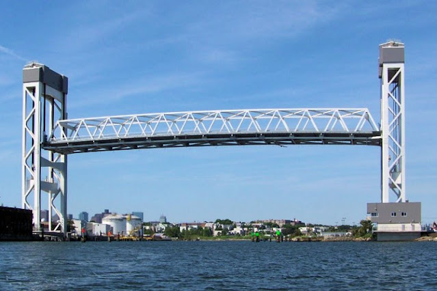
"The new bridge is the largest permanent lift bridge built in Massachusetts to date." [FINLEY]
 |
| Street View |
July 2008 of Google Earth shows no signs of construction. The next view is Jun 2010 and the north tower appears to be complete and they are erecting the south tower.
 |
| Google Earth, Jun 2010 |
By December, the south tower appears to be complete.
 |
| Google Earth, Dec 2010 |
I include the ship in this image so that you can compare the width of the ship to that of the navigation span. Northeast of the north tower we see the fabricated trusses. Normally, the truss is built offsite and floated into place. The reason the truss units were built onsite is described further below.
The width of the navigation span was 96' (30m). The new bridge "consists of a massive constant-height warren-type steel truss that spans 450 ft (137m) between two, 216 ft (65m) high towers, and when raised gives 175 ft (53m) of vertical clearance for shipping." [lusas]
 |
| Google Earth, Apr 2011 |
By Aug 2013, the new bridge appears to be done. I don't know why Bridge Hunter uses a built year of 2014. (In fact, it was opened May 14, 2012.)
 |
| Google Earth, Aug 2013 |
Why were the truss units built onsite?
Because there was not enough clearance in the channel to float in a completed 450' truss. Since they could not float the truss into place, they built it in two pieces next to the road. In addition to building the trusses, they designed and built launch rails over the old piers. When the truss units were ready, they moved one sideways to the launch rails and then moved it along the launch rails to make room to move the second unit on the rails. After joining the two units, they pushed the truss along the launch rails until it was in position. They then hooked up the tower cables and lifted it up out of the way. When they shoved the truss along the launch rails, the far end would be cantilevered over the navigation channel until the far end reached the rails on the other side. Once the end of the truss was over the channel, they had only 60 hours to finish shoving the truss to the other side and raise it clear of the channel.
 |
| lusas |
I presume that the industry now has software that automatically designs trusses. Given a few parameters such as the length, width, minimum height and expected traffic loads, I would expect the software to spit out the fabrications specs for all of the truss members and gusset plates. It would also expect the program to generate instructions for drilling machines to drill all of the necessary bolt holes. But that truss design would assume the truss is supported at each end. During construction, the truss would not be supported at the far end when it is cantilevered across the channel. Since the truss is designed to handle a traffic load, it would make sense that an empty truss would be strong enough to handle the unusual truss member loads when it is cantilevered over the channel. But FINLEY used some general purpose finite-element design software to verify that the forces didn't exceed the strength of any of the truss members.
 |
| lusas |
It looks like they are near launching the truss across the river.
 |
| FINLEY, 1 of 21 |
They built the towers with some pretty big subassemblies. I presume they have to stop traffic over the bridge when they do the lifts. So bigger subassemblies require fewer lifts, which require fewer traffic interruptions.
 |
| FINLEY, 10 of 21 |
It looks like they are close to closing the bridge to traffic so that they can build the launch rails and move the trusses onto the rails.
 |
| FINLEY, 21 of 21 |
This is the post that motivated researching this bridge. The driver was lucky that she didn't get caught on the former bascule bridge. That would have been much more perilous as the bridge went up. The article reports that when the bridge came back down and the gates went up, she simply continued on her way.
 |
| safe_image for 2 MassDOT contractors off the job after driver gets trapped on drawbridge |
No comments:
Post a Comment