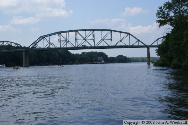
On my June 27 trip to Marseilles, I ended up traveling from Marseilles to Seneca on the south side of the Illinois River. I spotted a caboose near the river, so I got off the main road to take a picture of it. It turned out to be a private residence, so I did not take that picture. But I did find a nice riverside view of the Seneca road bridge.
 |
| 20140727 0078 |

Note that the 50 foot clearance is on a day when the William G. Stratton State Park in Morris, IL, was closed because of flooding.
I missed catching the steel truss bridge by a few years. John's site indicates the steel truss bridge was built in 1932.
 | ||
| John Weeks III |
 | ||
| John Weeks III |
 |
| Seneca Photo Collection |
 | ||
| 1937-47, http://maps.isgs.illinois.edu/ilhap/, the left side is the south side. |


At web resolutions, it is even hard to see the bottom plate of the field joint, so I added red lines to mark the field joints.

John indicated that the new bridge was to have a main span of 350-375 feet. (The distance of the right full beam seems smaller than the other two. And the beam in the middle is a little longer. Is that some sort of optical illusion?) The two short segments on each side are about half a beam. So the main span is about 4 beams. 350/4 is 87.5 feet. When I researched bending beams, I came across the factoid that beams were up to 26 meters long. Using a conversion tool, that is about 85 feet. One advantage of building a bridge across a navigable body of water is that you can ship the beams to the site using a barge. I wonder if these beams were transported by truck or barge.
The three "pipes" hanging down hold clearance markers.
I assume that the two red squares on the side of the beams are daytime clearance indicators. At first I was surprised that the piers were not protected by fenders. Then I realized it was reasonable to expect pilots to be able to fit a 110 foot wide tow between piers over 300 feet apart without a problem. I wonder if tows in opposite directions would avoid meeting under a bridge. Or maybe modern piers for these large steel spans are massive enough that they are effectively fenders themselves.
No comments:
Post a Comment