Joseph Strauss graduated from the University of Cincinnati in 1892. His career soon took him to Chicago. After working on the project by the Sanitary District to reverse the flow of the Chicago River, he "became a Principal Assistant Engineer in charge of the Chicago office of Modjeski & Angier." He was charged with studying the use of bascule bridges because the War Department declared the swing bridges in the Chicago River had to be replaced. Modjeski did not like his plan so he resigned and joined Rall Bascule Bridge Co. as the Chief Engineer. After a year there, in 1902 he started his own Strauss Bascule & Concrete Bridge Co. He built his first bridge for the Wheeling & Lake Erie Railroad in 1904-05. It was the first bascule bridge to use concrete instead of cast iron or even more expensive materials for the counterweight. But concrete was not as dense, thus it required a bigger counterweight. Rather than make the watertight tail pit bigger, which would be more expensive, he mounted the counterweight high above the tracks to completely eliminate the expense of the tail pit. [StructureMag]
.jpg) |
| Figure via TheStraussBasculeBridgeCo via BridgeHunter, cropped via Dennis DeBruler See Dennis DeBruler for a patent diagram |
 |
| Douglas Butler posted The Strauss Bascule Bridge Company chief engineer Joseph B. Strauss also designed popular bascule bridges over 400 drawbridges. Three types you see here, the Overdeck or Overhead Counterweight Trunnion Type on the right, the Underdeck or Underneath Counterweight Trunnion type on the left and the Heel Trunnion Type the bottom. Joseph Strauss had some rivals with Albert Scherzer of the bascule bridges being more active, there are competitors of engineers and inventors throughout the 1900's 1920's to the 1960's after Strauss's death in 1937 after completing the Golden Gate Bridge in San Francisco CA. Strauss designed also fixed bridges some swing and vertical lift bridges. |
He quickly simplified the design to mounting the counterweight vertically behind a support tower to form a parallelogram. And the machinery room is beneath the bridge instead of on top of a tower. A curved rack under the counterweight end of the span is used instead of an operational strut.
 |
| Otis Ellis Hovey, Movable Bridges, p.117 via HAER-data, p16 via Dennis DeBruler |
Here is another diagram. I presume that R is the rack and P is the pinion. Note that the main trunnion, G, is high above the foundation compared to other bascule designs. In this document, G is also used to denote the center of gravity.
 |
| Google eBook via Bridge Hunter |
By 1908, he had scaled up his design to serve a double-track railroad bridge for the C&NW.
 |
| Street View |
 |
| HAER IL-142, p. 18, initial design, Kinzie (Wells) |
 |
| 20150513 1427 The St. Charles Air Line Bridge is in the foreground, and the B&OCT Bridge is in the background. The St. Charles Air Line Bridge was built in 1919 over the original South Branch river bed, and it was 260' long. Today it spans the straignted river bed and is "just" 220' long. |
 |
| 20150502 9639, digitally zoomed to camera resolution |
 |
| HAER IL-157, p. 19, climax design, St. Charles Airline |
I wondered why I could not see an elephant ear on this side of the B&OCT bridge in the above photo. The photo below explains why. Strauss chose to use a monolith counterweight for this bridge that was never longer than 220'.
 |
| Marty Bernard posted via Dennis DeBruler |
 |
| Street View, Jul 2019 If you look at a satellite map, this is now a bridge to nowhere because it was used for passenger service. Specifically, the tracks east of the bridge and west of Canal Street have been removed. |
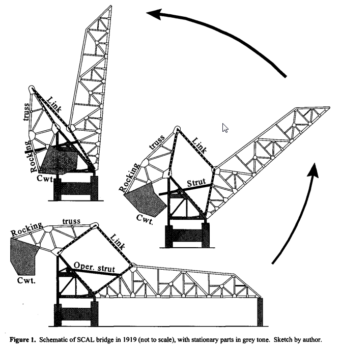
In this diagram, The member T-C-E is the right side of a fixed triangle setting on the piers. E is the trunnion of the movable span and T is the counterweight trunnion. Points F, T, H and E all pivot and they form the parallelogram that changes shape was the span raises. This diagram has to be wrong because it shows the operating pinion on the movable span rather than on the fixed triangle. At the beginning of the 20th Century, they did not have remote control so the machinery house was also the control room. Unlike a lift bridge where the span remains horizontal, a control room on a bascule span would be a very interesting ride. Is this an example were the arthur includes a subtle error to catch copyright violations? (I remember a teacher explaining that not all of the answers in the back of a textbook are correct because it is an easy way to document copyright violations.)
 |
| Google: Waddell's 1916 Bridge Engineering eBook via Bridge Hunter |
 |
| HAER-data, p10 via Dennis DeBruler |
SUC bridges for which I have notes:
- 1922,1950 DCAX/(DTI+GTW) SUC Bridge over Short Cut Canal 21 (Rouge River) in Detroit, MI
- Dousman+Main Street (SUC) Bridges over Fox River in Green Bay, WI
- Gloucester Draw (SUC) Bridges over Annisquam River in Gloucester, MA
- Berkley Bridge over East Branch Elizabet River in Norfolk, VA This photo shows that Strauss switched to the curved rack quite a while ago.
- St. Andrews Dam
- StLIM&S SUC Bridge over Black River near Corning, AR
- 6th Street Bridge over Muskingum River Canal in Zanesville, OH
- Amtrak Bush River SUC Bridge at Perryman, MD
- MBTA SUC Bridge over Annisquam River in Gloucester, MA
- Polk Street Bridge in Chicago, IL
I used to think the overhead counterweight design was rare because I came across a lot of heel trunnion bridges before I saw any SOC designs. The first SOC design I saw was in Jul 18, 2020, the Walnut Street Bridge in Green Bay, WI. Then I saw my first still-standing bridge in Jul 23, 2020 in Zanesville, OH. I have learned that Straus used the OC design for small bridges and the heel trunnion design for large bridges. Small bridges tend to be used over small canals. Many small canals are no longer used. Since those bridges tended to be for roads, the states would replace them with fixed bridges since they get 80% federal funds for new bridges and 0% for fix an existing bridge. (Note that the Zanesville bridge is a railroad bridge. They generally don't get federal funds to build a new bridge.) Here is the Bridge Hunter list for SOC bridges.
B&O on Staten Island has a horizontal link in down position and an article that brags about
Notice the claim about "exactly balanced." That would be true in this case because the top and bottom cords of the parallelogram are horizontal when the span is down. The claims about "positively connected to the foundations" and "the loads are transmitted to the same point" are arguments in favor to trunnion designs and against his competitors' (Scherzer and Rall) designs.
.png) |
| Google: 1908 Railroad Gazette eBook via Bridge Hunter via Dennis DeBruler |
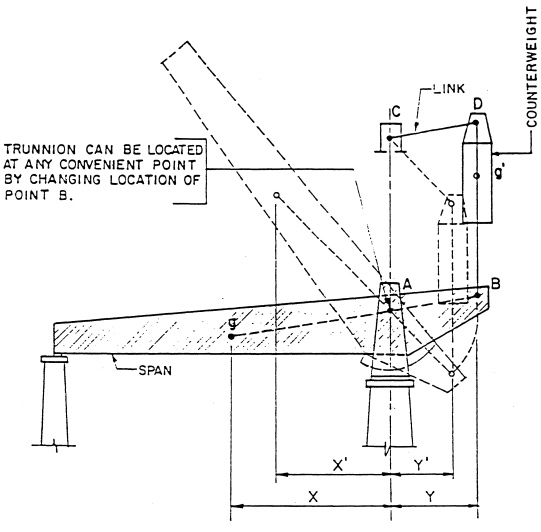
I think it is significant that the B&O bridge is the only one I have found where the short links are horizontal when the span is down. Normally those links are tilted a little bit above horizontal as depicted in both of the above diagrams. In the first diagram, note the distances X+Y (closed) and X'+Y' (partially open). I check a bascule bridge design to see how Y' shrinks as X' shrinks to keep the center of gravity over its pivot point. Likewise, as the span closes, X' and Y' should proportionally grow longer. The problem with a SOC design that has an angled short link is that Y' quits growing and actually shrinks as the link goes past 90-degrees. But X' continues to grow. Granted, the sin at 90-degrees changes slowly (sin 90 = 1 and sin of 95 = .996), but Y' is changing in the wrong direction. I don't see how the bridge can remain "exactly balanced." Note that in his heel trunnion design, the Y' does keep growing as X' grows.
SOC bridges for which I have notes:
- 1913 CUOH/B&O SOC Bridge over Canal in Zanesville, OH
- Walnut Street SOC Bridge over Fox River in Green Bay, WI
- 1895+1925(SOC)+1978 FEC Bridges over New River in Fort Lauderdale, FL
- 1925 SOC Bridge over Newport River in Morehead City, NC
- 1912 Trail/HB&T SOC Bridge over Buffalo Bayou in Houston, TX
- 1926+1992 SOC Bridges over Mullica River near Egg Harbor City, NJ
- B&O SOC Bridge over Bodine Creek in Staten Island
- 1919-1955 Lost/Boston & Albany SOC Bridge over Chelsea Creek at Chelsea, MA
- Green Mountain/Rutland Bridge over SOC Barge Canal in Burlington, VT
- Lost Mare Island Causeway SOC Bridges over Napa River in Vallejo, CA
- MBTA SOC Bridge over Saugus River at Lynn, MA
- 1909 Lost/(Ohio Electric and/or NKP) SOC Bridge over Swan Creek in Toledo, OH
- NYS&W/Erie SOC Bridge over Overpeck Creek near Hackensack River in Ridgefield Park, NJ
- 1917 Lost Pedestrian SOC Bridge over Mattawoman Creek
- 1926 Manthey Road/Lincoln Highway SOC Bridge over San Joaquin River in Lathrop, CA
- 1908 CN SOC Bridge over Rainy Lake near Fort Frances, ON Collapsed on Aug 14, 2024
- 1917 Pennsy and Reading SOC Bridges over Darby Creek THIS IS THE BEST ONE
- 1925 Hylebos Bridge in Tacoma, WA
- SOC and 1951 Double-Swing Bridges over North Landing River at Chesapeake, VA
No comments:
Post a Comment